


Instruction Manual
748297-E
June 2003
4-28 Maintenance and Troubleshooting Rosemount Analytical Inc. A Division of Emerson Process Management
Model NGA2000 HFID
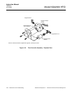
Fuel In 2-Way Solenoid Valve
1. Disconnect wiring solenoid valve wir-
ing connector, note location.
2. Inside the analyzer module, discon-
nect the tube going to the connector
on the “out” port of the solenoid valve.
3. On the rear of the analyzer module at
the fuel in port:
a. Disconnect the fuel in tube.
b. Remove nuts and washers.
4. Remove solenoid valve from analyzer
module
5. Remove the fittings from the solenoid
valve and replace the Teflon pipe
thread tape.
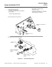
6. Verify that body of replacement sole-
noid valve is oriented as shown in
Figure 4-22 on page 4-27. If not, ro-
tate till wires are in-line with “out” port.
7. Install fittings into replacement sole-
noid valve, re-install in analyzer mod-
ule.
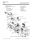
Burner Air In Filter
1. Leaving the bulkhead fitting secured
to the rear panel, remove the tubes,
nuts and ferrules from the fitting.
2. Insert a clean, rigid piece of tube or
rod (smaller than .25 inch diameter)
into the bulkhead fitting to force out
the filter disc.
3. Install the replacement filter in the
same manner, through the rear of the
bulkhead fitting.
4. Re-connect tubes.
Heated Bypass Sample Out and Heated
Sample In Restrictors
1. On the outside of the rear panel, dis-
connect tube and remove nut.
2. Insert a small spade screwdriver into
the bulkhead and remove the restric-
tor.
3. Install in reverse order.
Regulated Air In Check Valve
1. Disconnect tube at elbow.
2. Remove check valve from female
connector.
3. Remove elbow from check valve.
4. Add Teflon pipe thread tape to check
valve threads.
5. Install elbow onto check valve.
6. Install check valve into female con-
nector, verifying orientation of elbow
fitting as shown in Figure 4-22 on
page 4-27.