


Instruction Manual
748297-E
June 2003
4-6 Maintenance and Troubleshooting Rosemount Analytical Inc. A Division of Emerson Process Management
Model NGA2000 HFID
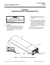
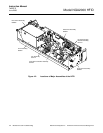
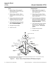
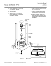
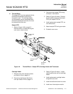
The components shown can be replaced without removing burner/thermal block from oven. Oven not shown for clarity.
Thermal block shown in phantom for clarity.
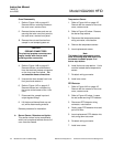
Set Screw
M3X0.5 x 10mm
903125
RTD Detector
657063
Ignitor Assembly
657205
O-Ring
903736
O-Ring
903737
Flameout Sensor
657199
Temperature Sensor
657468
Retainer, Burner Cap
Burner Cap
Ignitor
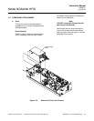
1. Refer to Figure 4-4A on page 4-5.
Remove the four screws on the oven
cover, remove cover.
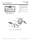
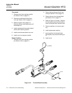
2. Refer to Figure 4-5 below. Discon-
nect the ignitor wiring connector, note
location.
3. Using an open-end wrench, unscrew
the ignitor assembly from the burner.
Verify that o-ring is also removed.
4. Install replacement ignitor and new o-
ring. Using open-end wrench, snug
down. Do not over-tighten!
5. Re-attach wiring connector.
6. Install oven cover
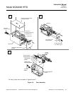
Flameout Sensor
1. Refer to Figure 4-4A on page 4-5.
Remove the four screws on the oven
cover, remove cover.
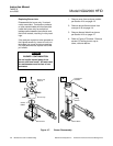
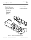
2. Refer to Figure 4-5 below. Discon-
nect the flameout detector wiring con-
nector, note location.
3. Lift up the burner cap until flameout
sensor is accessible. Using an open-
end wrench, unscrew the flameout
detector from the burner. Verify that
o-ring is also removed.
4. Install replacement flameout detector
and new o-ring. Using open-end
wrench, snug down. Do not over-
tighten!
5. Re-attach wiring connector.
6. Install oven cover.
Figure 4-5. Burner - Sensor, Flameout Detector, RTD Detector and Ignitor