


Instruction Manual
748297-E
June 2003
Rosemount Analytical Inc. A Division of Emerson Process Management Installation
2-1
Model NGA2000 HFID
SECTION 2
INSTALLATION
2-1 UNPACKING
Carefully examine the shipping carton and con-
tents for signs of damage. Immediately notify
the shipping carrier if the carton or its contents
are damaged. Retain the carton and packing
material until the instrument is operational.
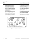
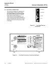
2-2 ASSEMBLY
If the Analyzer Module requires assembly with
other components, do so at this time.
Connect the network cable to either the NET-
WORK 1 or NETWORK 2 connection on the
Analyzer Module. Connect the power cable to
the Analyzer Module front panel and an electri-
cal +24VDC power supply.
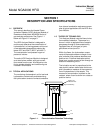
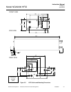
2-3 LOCATION
Install the Analyzer Module in a clean,
weather-proofed, non-hazardous, vibration-free
location free from extreme temperature varia-
tions. For best results, install the Analyzer Mod-
ule near the sample stream to minimize sample
transport time.
WARNING
INSTALLATION RESTRICTIONS
For safety, the Analyzer Module should be
installed in a non-confined, ventilated space.
Do not block any of the rear panel outlets as
they are part of the safety system.
Operating ambient temperature is 15°C to
35°C, limited to temperature changes of less
than 10°C/hr. Acceptable dew point range is
less than 95% relative humidity, but not in ex-
cess of 45°C wet bulb temperature.
The cylinders of fuel, air, and calibration gas(es)
and the source of purge and regulated air
should be located in an area of relatively
constant ambient temperature.
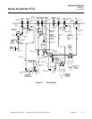
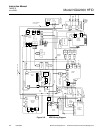
2-4 GASES
a. Overview
During normal operation, the Analyzer
Module requires fuel and air to maintain
the burner flame as well as suitable
standard gases for calibration and in-
strument air for purge requirements. In
addition, instrument air for regulated air
in is required to control the sample
pressure at the sample capillary. Crite-
ria for selection of these gases follow in
this section.
After initial startup or after startup fol-
lowing a prolonged shutdown, the ana-
lyzer may display baseline drift for a
considerable period of time, particularly
on the most sensitive range. Com-
monly, the drift is caused by small
amounts of hydrocarbons in the inner
walls of the tubing in both the internal
flow system and the external gas supply
system. Drift results from any factor in-
fluencing the equilibrium of these ab-
sorbed hydrocarbons, such as
temperature or pressure.
Note that this type of drift occurs only
when the flame is burning. If drift occurs
when the flame is extinguished, the
electronic circuitry is at fault. To mini-
mize drift, use clean fuel and air, keep
the analyzer clean, and locate the gas
cylinders in an area of relatively con-
stant ambient temperature.
The cylinders supplying all gases each
should be equipped with a clean, hy-
drocarbon-free, two-stage regulator and
a shutoff valve.