


Instruction Manual
748297-E
June 2003
Rosemount Analytical Inc. A Division of Emerson Process Management Description and Specifications
1-1
Model NGA2000 HFID
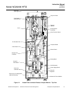
Positive
Carbon
Ions
Signal Conditioning
Negative Ion
Collection Plate
Sample
Air
Fuel
+90V
SECTION 1
DESCRIPTION AND SPECIFICATIONS
1-1 OVERVIEW
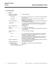
This manual describes the Heated Flame
Ionization Detector (HFID) Analyzer Module of
Rosemount Analytical's NGA2000 Series of
gas analysis components. See Figure 1-1
below and Figure 1-2 on page 3.
The HFID Analyzer Module is designed to
continuously determine the concentration of
hydrocarbons in a flowing gaseous mixture at
a user-selectable temperature setpoint be-
tween 93°C and 204°C (200°F and 400°F).
The concentration is expressed in ppm or
percent of volume.
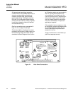
The entire HFID Analyzer Module is designed
as a stand-alone module, with gas connec-
tions made from the rear. All electronics rela-
tive to sample detection and conditioning are
included in this module.
1-2 TYPICAL APPLICATIONS
The monitoring of atmospheric air for low-level
hydrocarbon contaminants and determining
the hydrocarbon content of exhaust emissions
from internal combustion engines are exam-
ples of typical applications for the HFID Ana-
lyzer Module.
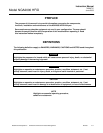
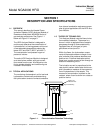
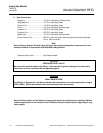
1-3 THEORY OF TECHNOLOGY
This Analyzer Module uses the flame ioniza-
tion method of detection. The sensor is a
burner in which a regulated flow of sample
gas passes through a flame sustained by
regulated flows of a fuel gas (a hydro-
gen/diluent mixture) and air.
Within the flame, the hydrocarbon compo-
nents of the sample stream undergo a com-
plex ionization that produces electrons and
positive ions. Polarized electrodes collect
these ions, causing current to flow through an
electronic measuring circuit.
The ionization current is proportional to the
rate at which carbon atoms enter the burner,
and is therefore a measure of the concentra-
tion of hydrocarbons in the sample. This
measure of concentration is placed on the
network, where it can be shown on a data ac-
quisition device.
Figure 1-1. Flame Ionization Detection Technology