


Instruction Manual
748297-E
June 2003
4-24 Maintenance and Troubleshooting Rosemount Analytical Inc. A Division of Emerson Process Management
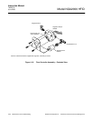
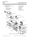
Model NGA2000 HFID
LON/Power Module
1. Disconnect wiring connectors, note
locations.
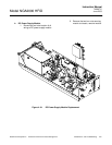
2. Refer to Figure 4-20 on page 4-22.
From the outside of the front panel,
remove the two mounting screws.
3. Install replacement module in reverse
order.
LED Indicator Assembly
1. Disconnect wiring connector, note lo-
cation.
2. Refer to Figure 4-20 on page 4-22.
From the inside of the front panel,
remove the two hex nuts securing
LED indicator assembly to front panel.
Remove indicator assembly and o-
rings (four).
3. Inspect o-rings for damage, replace if
necessary. Install o-rings on re-
placement indicator assembly, mount
assembly on mounting studs with hex
nuts.
4. Re-connect wiring connector.
Manual Ignite Toggle Switch
1. Disconnect wiring connector, note lo-
cation.
2. Refer to Figure 4-20 on page 4-22.
From the outside of the front panel,
remove the toggle switch seal.
3. Pull the switch and o-ring out from in-
side the front panel.
4. Inspect o-ring for damage, replace if
necessary. Install o-ring on replace-
ment switch, insert through front
panel from the inside.
5. Install switch seal.
6. Re-connect wiring connector.
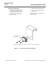
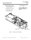
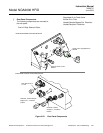
Burner Air Sensor
1. Disconnect wiring connector, note lo-
cation.
2. Using an open-end wrench to hold the
sensor fitting while using another
open-end wrench to remove the sen-
sor.
3. Replace the Teflon pipe thread tape
on the treads of the sensor fitting.
4. Install sensor onto sensor fitting.
5. Re-connect wiring connector.
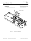
Fuel Sensor
1. Disconnect wiring connector, note lo-
cation.
2. Using an open-end wrench to hold the
sensor fitting while using another
open-end wrench to remove the sen-
sor.
3. Replace the Teflon pipe thread tape
on the treads of the sensor fitting.
4. Install sensor onto sensor fitting.
5. Re-connect wiring connector.