


Instruction Manual
748297-E
June 2003
Rosemount Analytical Inc. A Division of Emerson Process Management Contents iii
Model NGA2000 HFID
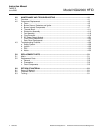
LIST OF ILLUSTRATIONS
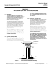
Figure 1-1.
Flame Ionization Detection Technology ................................................................ 1-1
Figure 1-2. Heated Flame Ionization Detector Analyzer Module – Top View.......................... 1-3
Figure 2-1. Back Panel Connections........................................................................................ 2-2
Figure 2-2. Flow Diagram......................................................................................................... 2-5
Figure 2-3. Front Panel Electrical Connections ....................................................................... 2-6
Figure 2-4. Front Panel Connections, Controls and Indicators................................................ 2-6
Figure 2-5. HFID Outline and Mounting Dimensions ............................................................... 2-7
Figure 2-6. HFID Wiring Diagram............................................................................................. 2-8
Figure 3-1. Typical Curves of Module Response vs. Pressure Setting on Fuel Pressure
Regulator ............................................................................................................... 3-7
Figure 3-2. Typical Curves of Module Response vs. Pressure Setting on Air Pressure
Regulator ............................................................................................................... 3-7
Figure 3-3. Front Panel Torquing Sequence............................................................................ 3-8
Figure 4-1. Removal of Cover and Insulation Shield ............................................................... 4-1
Figure 4-2. Locations of Major Assemblies of the HFID .......................................................... 4-2
Figure 4-3. Removal of Oven from Chassis............................................................................. 4-3
Figure 4-4. Oven Assembly...................................................................................................... 4-5
Figure 4-5. Burner - Sensor, Flameout Detector, RTD Detector and Ignitor ........................... 4-6
Figure 4-6. Burner/Thermal Block Disassembly....................................................................... 4-7
Figure 4-7. Burner Disassembly............................................................................................... 4-8
Figure 4-8. Burner Jets............................................................................................................. 4-9
Figure 4-9. Thermal Block – Sample RTD, Cartridge Heater and Thermostat...................... 4-11
Figure 4-10. Thermal Block Assembly ..................................................................................... 4-12
Figure 4-11. Removing Electronics Assembly from Chassis ................................................... 4-13
Figure 4-12. Electronics Assembly – Exploded View............................................................... 4-14
Figure 4-13. Case Sensor Installation...................................................................................... 4-15
Figure 4-14. Case Pressure Purge Switch Installation ............................................................ 4-16
Figure 4-15. Preamp Assembly Installation ............................................................................. 4-17
Figure 4-16. Fan Assembly Installation.................................................................................... 4-18
Figure 4-17. Flow Controller Replacement .............................................................................. 4-19
Figure 4-18. Flow Controller Assembly – Exploded View........................................................ 4-20
Figure 4-19. DC Power Supply Module Replacement ............................................................. 4-21
Figure 4-20. Front Panel – Exploded View .............................................................................. 4-22
Figure 4-21. Accessing Front Panel Components ................................................................... 4-23
Figure 4-22. Rear Panel Components ..................................................................................... 4-27
LIST OF TABLES
Table 3-1. HFID Analyzer Module Alarms .............................................................................. 3-8