14
Be careful to assemble all components
in the sequence they are presented.
STEP
A. See Diagram 1A. Attach Multi Hip Cable (40) to the Multi Hip Adjuster (AC) as shown using:
One 58 (5/16” x 1 1/2” hex head bolt)
One 63 (7/16”L spacer sleeve)
Two 2 (1/4”L spacer sleeve)
One 68 (5/16” nylon lock nut)
B.
Remove one of the pre-installed 3” Pulleys (36), either Pulley (C1) or Pulley (C2).
Route Cable (40) between the two 3” Pulleys (36), and reinstall 3” Pulley (36).
C.
See Diagram 1. Route Cable (40) down
along the Multi Hip Vertical Frame (P), and through the
opening in the Multi Hip Vertical Frame (P).
Install Pulley (C3) into the opening in Multi Hip Vertical Frame (P) over Cable (40) as shown in
Diagram 2 using:
One 53 (3/8” x 2 1/2” hex head bolt)
T
wo 5 (pulley spacer)
One 67 (3/8” nylon lock nut)
D.
See Diagram 1. Route Cable (40) around Pulley (C4) and install Pulley (C4) to the pulley flanges on
Multi Hip Base (N) as shown in Diagram 2 using:
One 51 (3/8” x 1 3/4” hex head bolt)
T
wo 70 (3/8” washer)
One 67 (3/8” nylon lock nut)
E.
See Diagram 1. Route Cable (40) up
to Pulley Holder (CB) and attach to the open hook on the
bottom of Pulley Holder (CB).
NOTE:
Leave all hardwar
e finger tight. Do not
wrench tighten hardware until after the final
cable adjustments are complete in Step 15.
mm
Inch
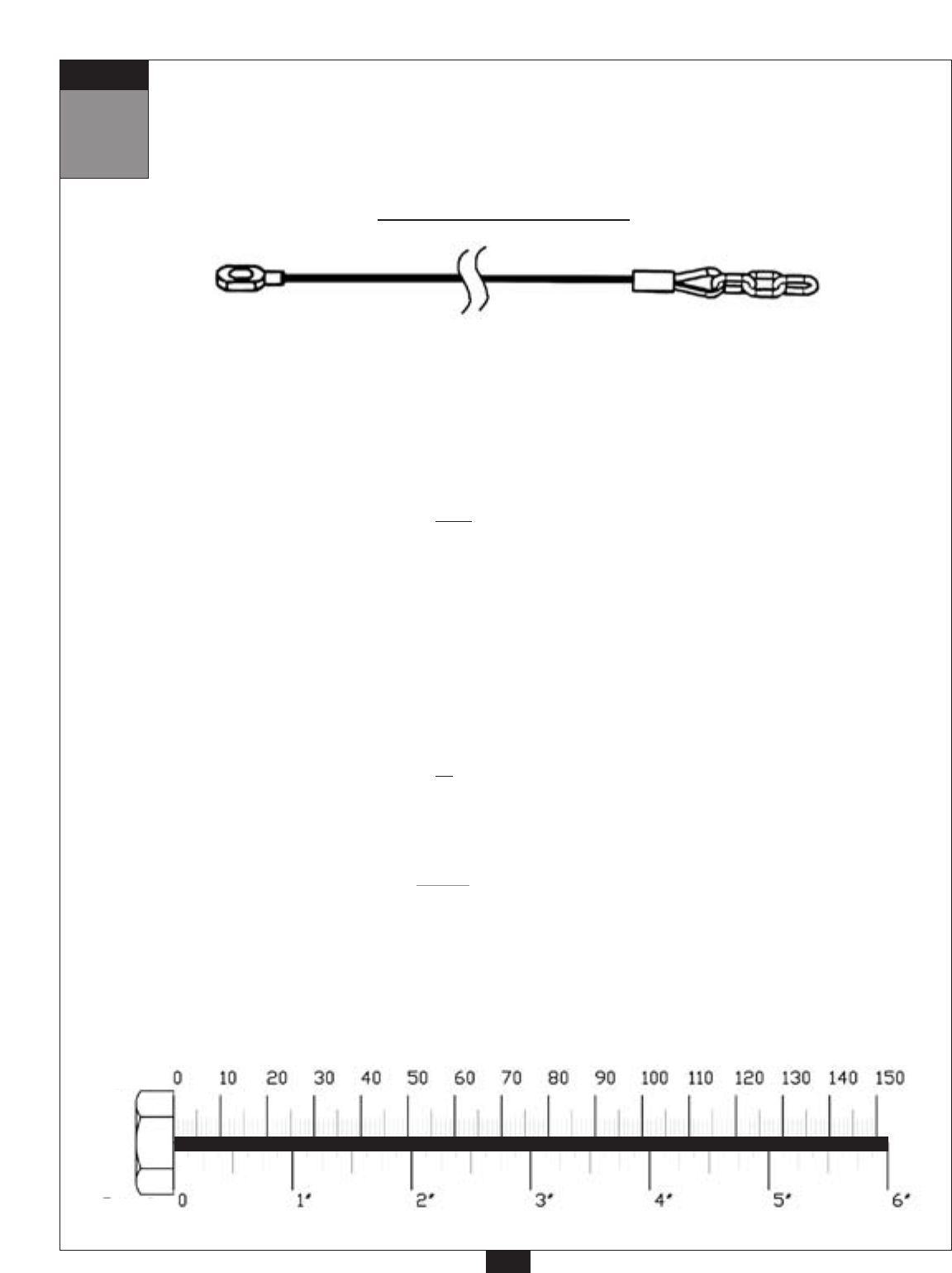
Multi Hip Cable (40)
1790 mm 5’ 10”
Stamped Eye End
Chain End
36


