10
Be careful to assemble all components
in the sequence they are presented.
mm
Inch
28
STEP
Note:
All Pulleys in this step are 4 1/4” diameter, except where noted in step 10B*.
Leave all pulley bolts hand tight until step 15 is completed.
A. See Diagram 1. Begin at the high pulley station. Route the High Pulley Cable (37) up
through
the first opening where pulley (A1) will be installed, and out through the top. Route Cable (37)
through the opening under the Bi-Angular Bars (Z) and then down
through the second opening
where pulley (A2) will be installed. Pull the entire length of cable through.
B. See Diagram 2. Insert one Pulley (A1)*, into the first opening in Top Main Frame (E) under
Cable (37) and attach using:
One 53 (3/8” x 2 1/2” hex head bolt)
T
wo 5 (pulley spacer)
One 67 (3/8” nylon lock nut)
*For Pulley (A1) use 3 1/2” diameter Pulley (KEY #35 on page 77).
C.
See Diagram 2. Inser
t one Pulley (A2), into the second opening in Top Main Frame (E) under
Cable (37) and attach using:
One 53 (3/8” x 2 1/2” hex head bolt)
T
wo 5 (pulley spacer)
One 67 (3/8” nylon lock nut)
D.
See Diagram 1. Route Cable (37) over
and around pre-installed Pulley (A3).
Route Cable (37) around Pulley (A4) and install Pulley (A4) onto the Angled Vertical Frame (D) as
shown in Diagram 2:
One 51 (3/8” x 1 3/4” hex head bolt)
T
wo 70 (3/8” washer)
One 67 (3/8” nylon lock nut)
E.
See Diagram 1. Route Cable (37) over
and around pre-installed Pulley (A5).
Route Cable (37) around Pulley (A6) and install Pulley (A6) into the Angled Vertical Frame (D) as
shown in Diagram 2:
One 53 (3/8” x 2 1/2” hex head bolt)
T
wo 5 (pulley spacer)
One 60 (3/8” nylon lock nut)
NOTE:
Leave all har
dware finger tight. Do not
wrench tighten hardware until after the final
cable adjustments are complete in Step 15.
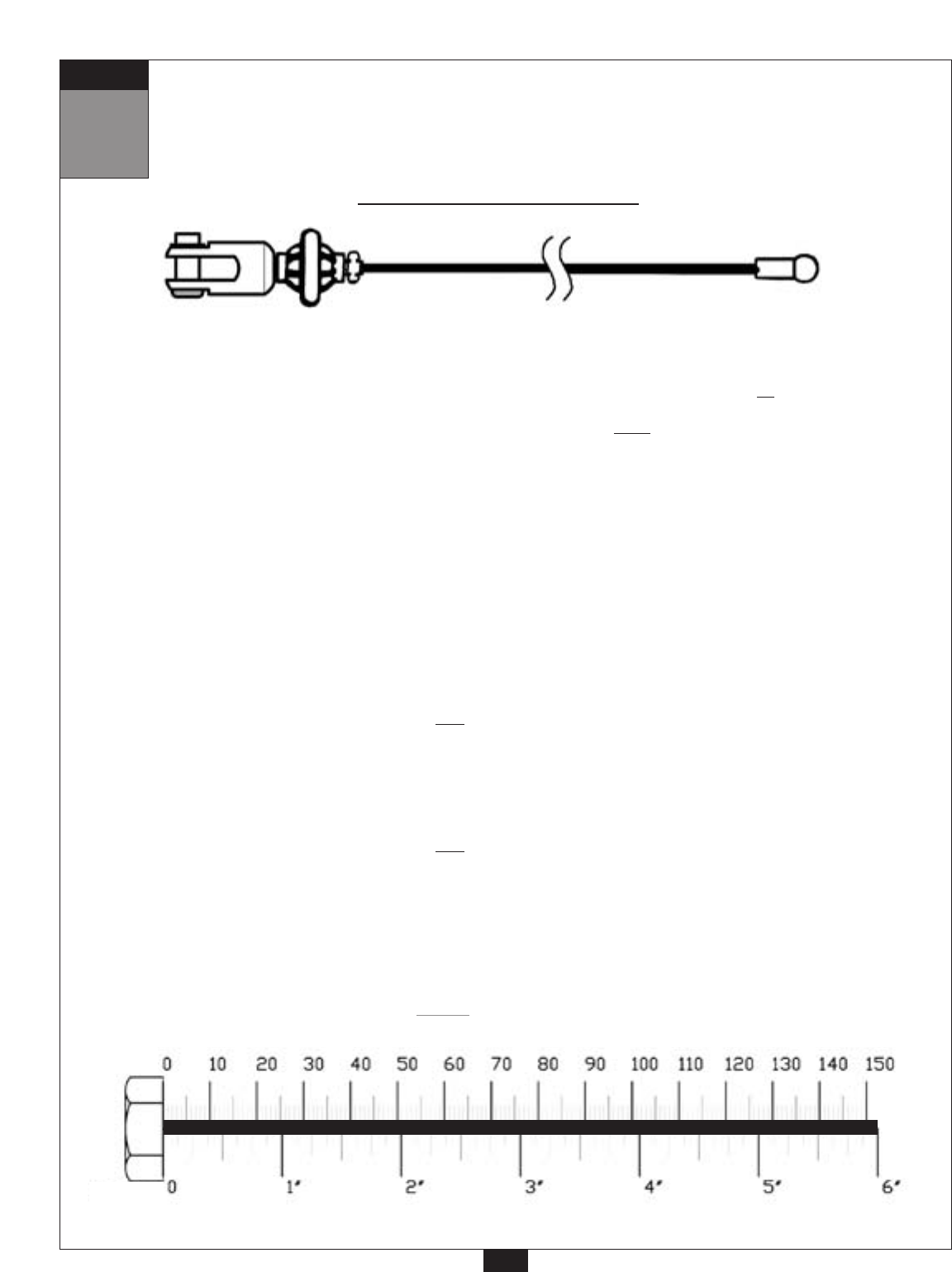
Ball Stop End Metal Ball End
3916 mm
12’ 10”
High Pulley Cable (37)


