


12
STEP
Be careful to assemble all components
in the sequence they are presented.
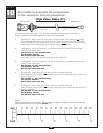
mm
Inch
32
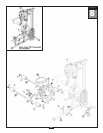
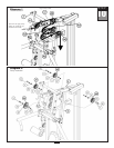
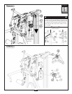
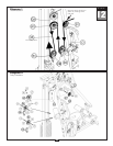
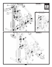
Note:
All Pulleys in this step are 4 1/4” diameter, except where noted in step 12B*.
Leave all pulley bolts hand tight until step 15 is completed.
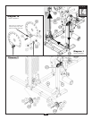
A. See Diagram 1. Insert either end of the Ab Crunch Cable (38) into the opening in Angled
Ver
tical Frame (D), above Back Pad (BB), and pull entire length through.
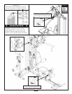
B. Install *3 1/2” Diameter Pulley (B1), under
Cable (38) and into Angled Vertical Frame (D) as
shown in Diagram 2 using:
One 53 (3/8” x 2 1/2” hex head bolt)
Two 5 (pulley spacer)
One 67 (3/8” nylon lock nut)
C.
See Diagram 1. Route Cable (38) through the first Pulley Holder (CB).
Hold cable in place by installing Pulley (B2) as shown in Diagram 2 using:
One 51 (3/8” x 1 3/4” hex head bolt)
T
wo 70 (3/8” washer)
One 67 (3/8” nylon lock nut)
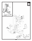
D.
See Diagram 1. Route Cable (38) up
through the bottom of Double Pulley Holder (CA).
Hold cable in place by installing Pulley (B3) as shown in Diagram 2 using:
One 51 (3/8” x 1 3/4” hex head bolt)
Two 70 (3/8” washer)
One 67 (3/8” nylon lock nut)
E.
See Diagram 1. Route Cable (38) through the other Pulley Holder (CB).
Hold Cable (38) in place by installing Pulley (B4) as shown in Diagram 2 using:
One 51 (3/8” x 1 3/4” hex head bolt)
T
wo 70 (3/8” washer)
One 67 (3/8” nylon lock nut)
NOTE:
Leave all har
dware finger tight. Do not
wrench tighten hardware until after the final
cable adjustments are complete in Step 15.
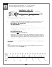
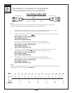
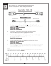
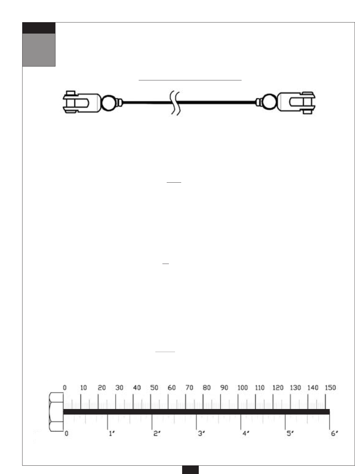
Low Pulley Cable (38)
6120 mm 20’ 9”
Small Ball End
Small Ball End