


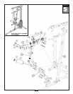
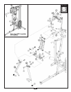
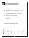
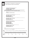
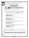
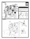

9
Be careful to assemble all components
in the sequence they are presented.
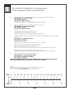
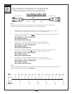
26
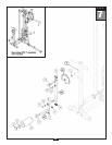
STEP
mm
Inch
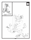
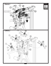
A. Attach Back Pad (BB) to Back Pad Frame (U) using:
Two 59 (5/16” x 1 3/4” hex head bolt)*
Two 72 (5/16” spring lock washer)
T
wo 73 (5/16” washer)
*Do NOT over-tighten pad bolts (59). Tighten these bolts until spring lock washer is flat.
Over - tightening these bolts will cause T - nuts in pads to strip out.
B. Attach Foot Brace (M) to the front of Main Base Frame (A) using Shaft (84) and the pre-installed
har
dwar
e:
Two 85 (5/16” x 5/16” allen screw)
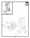
C. Insert two Pulleys (34) into the Press Arm Support (X) as shown using:
Two 57 (3/8” x 7 1/4” hex head bolt)
Four 1 (spacer sleeve)
Four 70 (3/8” washer)
T
wo 67 (3/8” nylon lock nut)
D.
Attach one Pulley (34) onto the flanges near the rear of Main Base Frame (A) as shown using:
One 51 (3/8” x 1 3/4” hex head bolt)
T
wo 70 (3/8” washer)
One 67 (3/8” nylon lock nut)
E.
Attach one Pulley (34) and Leg Extension Hook (104) onto the flanges near the front on
Main Base Frame (A) as shown using:
One 54 (3/8” x 2 3/4” hex head bolt)
Thr
ee 70 (3/8” washer)
One 103 (1/4” spacer)
One 105 (1/2” spacer)
One 67 (3/8” nylon lock nut)
F
. Attach two 3” Pulley (36) onto Multi Hip Vertical Frame (P) using:
Two 64 (3/8” x 2” hex head bolt)
T
wo 70 (3/8” washer)
T
wo 67 (3/8” nylon lock nut)
NOTE:
Leave all hardware finger tight. Do not
wrench tighten hardware until after the final
cable adjustments are complete in Step 15.