


11
Be careful to assemble all components
in the sequence they are presented.
30
STEP
mm
Inch
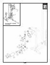
Note:
All Pulleys in this step are 4 1/4” diameter.
Leave all pulley bolts hand tight until step 15 is completed.
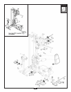
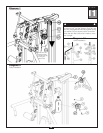
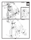
A. See Diagram 1. Route High Pulley Cable (37) through the top of Double Pulley Holder (CA) and
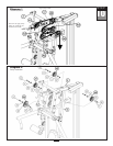
install Pulley (A7) into the top of Double Pulley Holder (CA) as shown in Diagram 2 using:
One 51 (3/8” x 1 3/4” hex head bolt)
T
wo 70 (3/8” washer)
One 67 (3/8” nylon lock nut)
Attach Rubber Pad (14) to the top of Double Pulley Holder (CA) as shown.
B.
See Diagram 1. Route Cable (37) up
and into the pulley holder on the Top Weight Stack Frame (R).
Installed Pulley (A8) under Cable (37) as shown in Diagram 2 using:
One 51 (3/8” x 1 3/4” hex head bolt)
Two 70 (3/8” washer)
One 67 (3/8” nylon lock nut)
Route Cable (37) down
towards the weight stack.
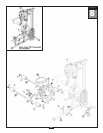
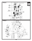
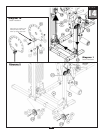
C. See Diagram 1A. First remove Allen Head Bolt (65). The Metal Ball End of Cable (37) should be
hanging just above the Weight Stack. slide Metal Ball End of Cable (37) through the Selector Rod
Top Bolt (98). Attach Cable End Shaft (99) and securely tighten Allen Screw (100). Pull Cable (37)
tight, so Cable End Shaft (99) fits securely inside Selector Rod Top Bolt (98). Install Allen Head
Bolt (65) in Selector Rod Top Bolt (98) and hold in place with Nylon Lock Nut (67).
Note:
Make sur
e the Selector Rod T
op Bolt (98) is threaded inside Selector Rod (33) at least
one half inch. Make sure Spring Lock Washer (101) is in place and wrench tighten Jam
Nut (102).
NOTE:
Leave all hardware finger tight. Do not
wrench tighten hardware until after the final
cable adjustments are complete in Step 15.
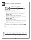
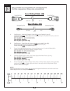
High Pulley Cable (37)
Ball Stop End
Metal Ball End
3916 mm 12’ 10”