


Be careful to assemble all components
in the sequence they are presented.
13
STEP
mm
Inch
34
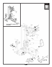
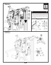
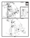
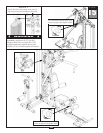
A. See Diagram 1. Route Leg Extension Cable (38) up to the Top Main Frame (E).
Install Pulley (B5) under
Cable (38) and into the pulley flange on Top Main Frame (E) as shown in
Diagram 2 using:
One 51 (3/8” x 1 3/4” hex head bolt)
Two 70 (3/8” washer)
One 67 (3/8” nylon lock nut)
B.
See Diagram 1. Route Cable (38) down and under
pre-installed Pulley (B6).
Route Cable (38) through the opening in Angled Vertical Frame (D).
Route Cable (38) under
pre-installed Pulley (B7).
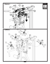
C. Route Cable (38) through the bottom of the Leg Extension Arm (L) and hold Cable (38) in
place by installing Pulley (B8) as shown in Diagram 2 using:
One 53 (3/8” x 2 1/2” hex head bolt)
T
wo 5 (pulley spacer)
One 67 (3/8” nylon lock nut)
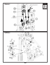
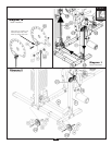
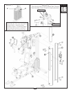
D.
See Short Cable Diagram. Attach Short Cable (39) to Main Base Frame (A) using:
One 55 (3/8” x 3” hex head bolt)
T
wo 70 (3/8” washer)
One 67 (3/8” nylon lock nut)
E.
Route Cable (39) up
to the front Pulley Holder (CB), the Pulley Holder (CB) that holds pulley (B2).
Attach the Flat Eye End of Cable (39) to the hook on the bottom of this Pulley Holder (CB) as
shown in Short Cable Diagram.
NOTE:
Leave all har
dwar
e finger tight. Do not
wrench tighten hardware until after the final
cable adjustments are complete in Step 15.
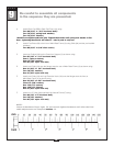
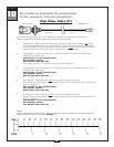
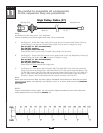
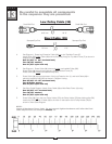
Low Pulley Cable (38)
6120 mm 20’ 9”
Small Ball End
Small Ball End
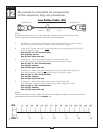
Short Cable (39)
Stamped Eye End
Stamped Eye End
757 mm 2’ 5”