


5
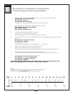
Be careful to assemble all components
in the sequence they are presented.
mm
Inch
18
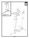
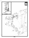
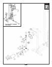
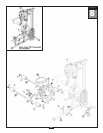
STEP
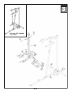
A. Slide two Nylon Bushings (13) into Back Pad Holder (S).
Attach Back Pad Holder (S) to Angled Vertical Frame (D) using:
Two 54 (3/8” x 2 3/4” hex head bolt)
Four 70 (3/8” washer)
Two 67 (3/8” nylon lock nut)
B.
Attach End Cap (17) to the end of Back Pad Adjuster (T).
Slide Back Pad Adjuster (T) into Back Pad Holder (S). Use the T
-Shaped Pop
Pin (106) and
One 91 (5/16” x 3/4” socket head allen bolt)
to hold in place.
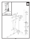
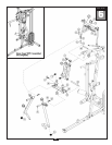
C.
Inser
t two End Caps (16) to the top and bottom of Back Pad Frame (U).
Attach Back Pad Frame (U) to Back Pad Adjuster (T) using the Pop Pin (90) and:
One 92 (3/8” x 5/8” allen bolt)
One 93 (3/8” washer)
D. Attach Leg Hold Downs (V) and (W) to the Angled Vertical Frame (D) as shown using:
Two 55 (3/8” x 3” hex head bolt)
Four 70 (3/8” washer)
T
wo 67 (3/8” nylon lock nut)
The Leg Hold Downs ar
e marked with an L and R to indicate left and right, They should angle
forwar
d and upwar
d.
E. Slide two Rollers (30) onto Right and Left Leg Hold Downs (V) and (W) and hold in place with two
Roller End Caps (41).
Note:
You should now wr
ench tighten all bolts and nuts in this step.