


6
Be careful to assemble all components
in the sequence they are presented.
mm
Inch
20
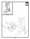
STEP
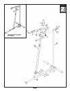
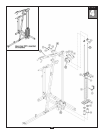
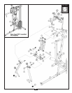
A. Attach Press Arm Support (X) to the Top Main Frame (E) using Shaft (88) and tighten
two Allen Screws (85).
Attach two Convex End Caps (17) to the top of Press Arm Support (X) as shown.
B. Attach Press Arm Pivot (Y) to Press Arm Support (X) using Shaft (89) and tighten
Two Allen Screws (85).
C. Attach Bi-Angular Bars (Z) to Top Main Frame (E) using:
Two 55 (3/8” x 3” hex head bolt)
Four 70 (3/8” washer)
T
wo 67 (3/8” nylon lock nut)
T
wo 60 (5/16” x 1/2” hex head bolt)
Two 74 (5/16” washer)
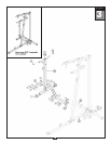
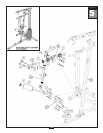
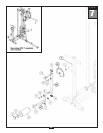
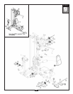
D. Attach Left Seated Press Arm (AA) to the Press Arm Pivot (Y) using Shaft (94) and:
One 95 (1/2” x 3/4” hex head bolt)
One 69 (1/2” washer)
Tighten two Allen Screws (85).
Attach Round End Cap (15) to the bottom of Left Seated Pr
ess Arm (AA).
E. Connect Left Seated Press Arm (AA) to the Bi-Angular Bars (Z) using Shaft (96) and:
Two 92 (3/8” x 5/8” hex head bolt)
T
wo 93 (3/8” washer)
F
. Attach Right Seated Press Arm (AB) to the Press Arm Pivot (Y) using Shaft (94) and:
One 95 (1/2” x 3/4” hex head bolt)
One 69 (1/2” washer)
Tighten two Allen Screws (85).
Attach Round End Cap (15) to the bottom of Right Seated Pr
ess Ar
m (AB).
G. Connect Right Seated Press Arm (AB) to the Bi-Angular Bars (Z) using Shaft (96) and:
Two 92 (3/8” x 5/8” hex head bolt)
T
wo 93 (3/8” washer)
Note:
Y
ou should now wr
ench tighten all bolts and nuts in this step.