1-55
Cisco ONS 15454 Installation and Operations Guide
November 2001
Chapter 1 Hardware Installation
Cable Routing and Management
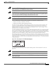
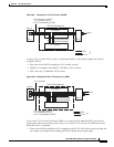
Note To remove the reels, take out the screw in the center of each reel.
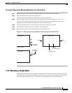
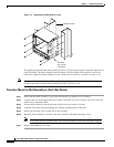
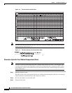
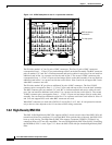
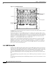
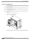
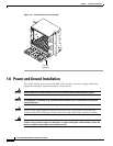
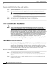
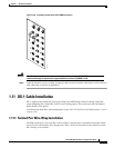
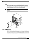
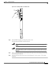
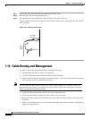
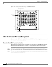
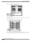
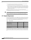
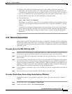
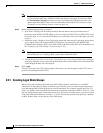
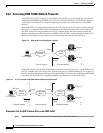
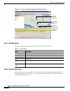
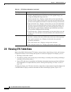
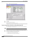
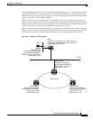
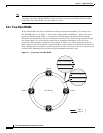
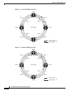
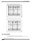
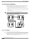
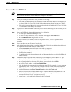
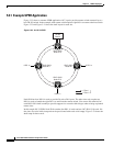
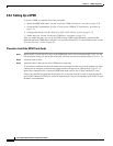
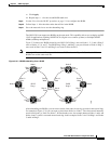
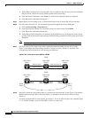
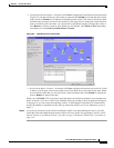
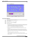
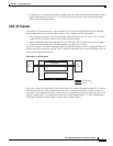
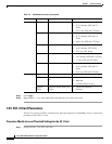
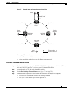
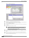
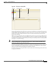
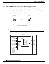
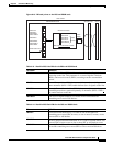
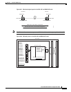
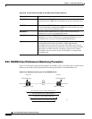
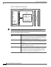
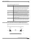
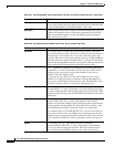
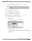
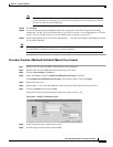
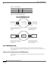
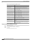
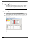
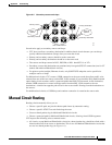
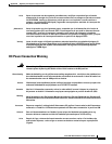
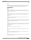
Figure 1-33 shows the cable management facilities that you can access through the fold-down front door,
including the cable-routing channel and the jumper routing fins.
Figure 1-33 Managing cables on the front panel
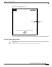
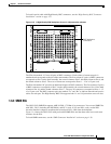
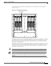
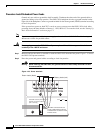
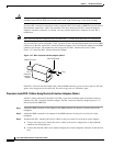
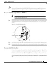
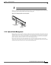
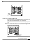
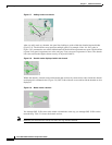
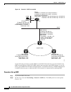
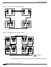
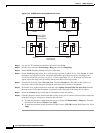
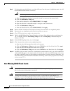
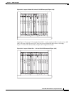
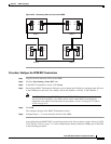
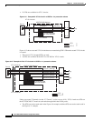
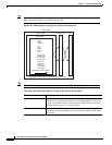
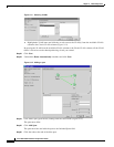
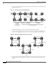
1.14.1 Optical Cable Management
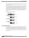
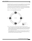
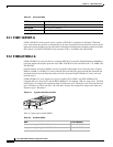
Optical cables connect to the SC connectors which are located on the faceplate of the optical cards and
on GBICs. Route optical cables down through the fiber management clips on the optical card faceplate
(shown in Figure 1-34) or, if the optical cables are connected to GBICs, route them down through the
jumper routing fins (Ethernet cards do not have fiber management clips).
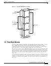
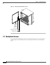
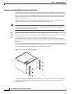
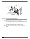
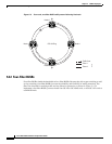
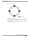
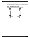
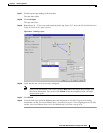
Route optical cables into the cable management area of the shelf assembly, through a cutout in the
nearest side of the assembly, and onto the side of the assembly. A hinged panel on the front of the shelf
assembly folds down to provide access to the cable-management tray.
F
A
N
F
A
IL
C
R
IT
M
A
J
M
IN
34238
Reversible jumper
routing fins
Fold down
front door