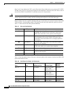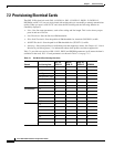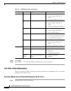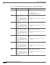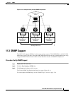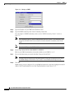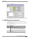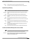
6-19
Cisco ONS 15454 Installation and Operations Guide
November 2001
Chapter 6 Circuits and Tunnels
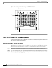
Cross-Connect Card Capacities
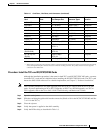
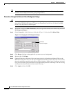
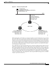
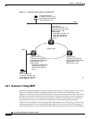
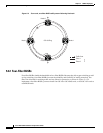
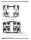
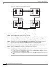
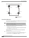
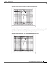
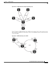
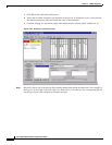
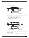
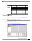
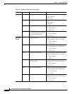
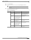
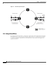
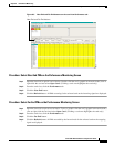
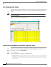
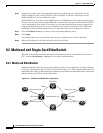
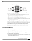
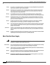
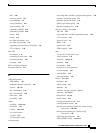
• In the Figure 6-10 example, three STSs are used at the source and drop nodes and four STSs are used
at pass-through nodes. In Figure 6-12, six STSs are used at the source and drop nodes and four
STSs at the pass-through nodes.
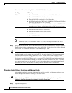
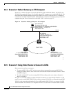
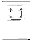
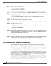
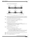
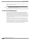
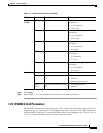
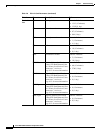
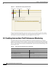
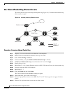
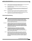
6.8.2 VT Tunnels
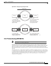
To maximize VT matrix resources, you can tunnel VT1.5 circuits through ONS 15454 pass-through
nodes (nodes that are not a circuit source or drop). VT1.5 tunnels provide two benefits:
• They allow you to route VT1.5 circuits through ONS 15454s that have XC cards. (VT1.5 circuits
require XCVT or XC10G cards at circuit source and drop nodes.)
• When tunneled through nodes with XCVT or XC10G cards, VT1.5 tunnels do not use VT matrix
capacity, thereby freeing the VT matrix resources for other VT1.5 circuits.
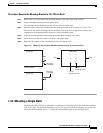
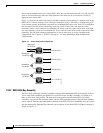
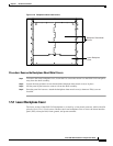
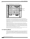
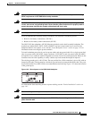
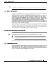
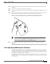
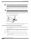
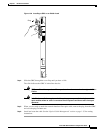
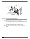
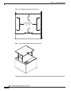
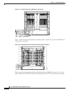
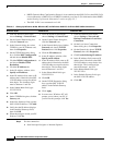
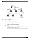
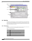
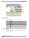
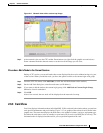
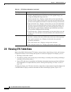
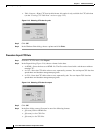
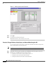
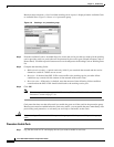
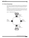
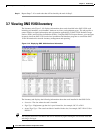
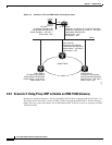
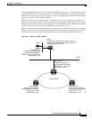
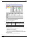
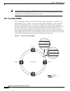
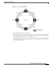
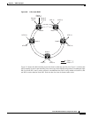
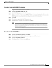
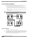
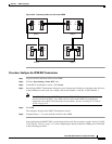
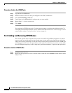
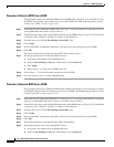
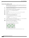
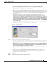
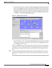
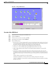
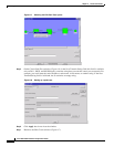
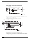
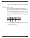
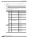
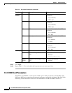
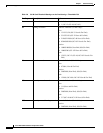
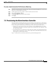
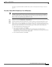
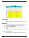
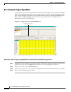
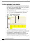
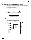
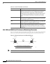
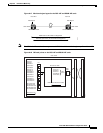
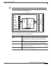
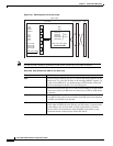
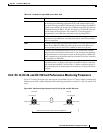
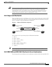
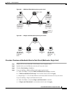
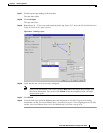
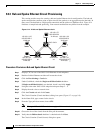
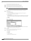
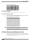
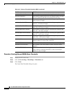
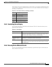
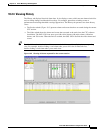
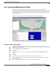
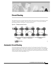
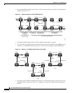
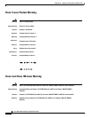
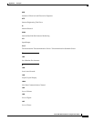
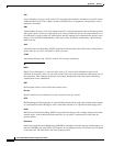
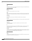
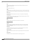
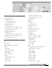
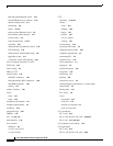
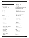
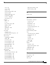
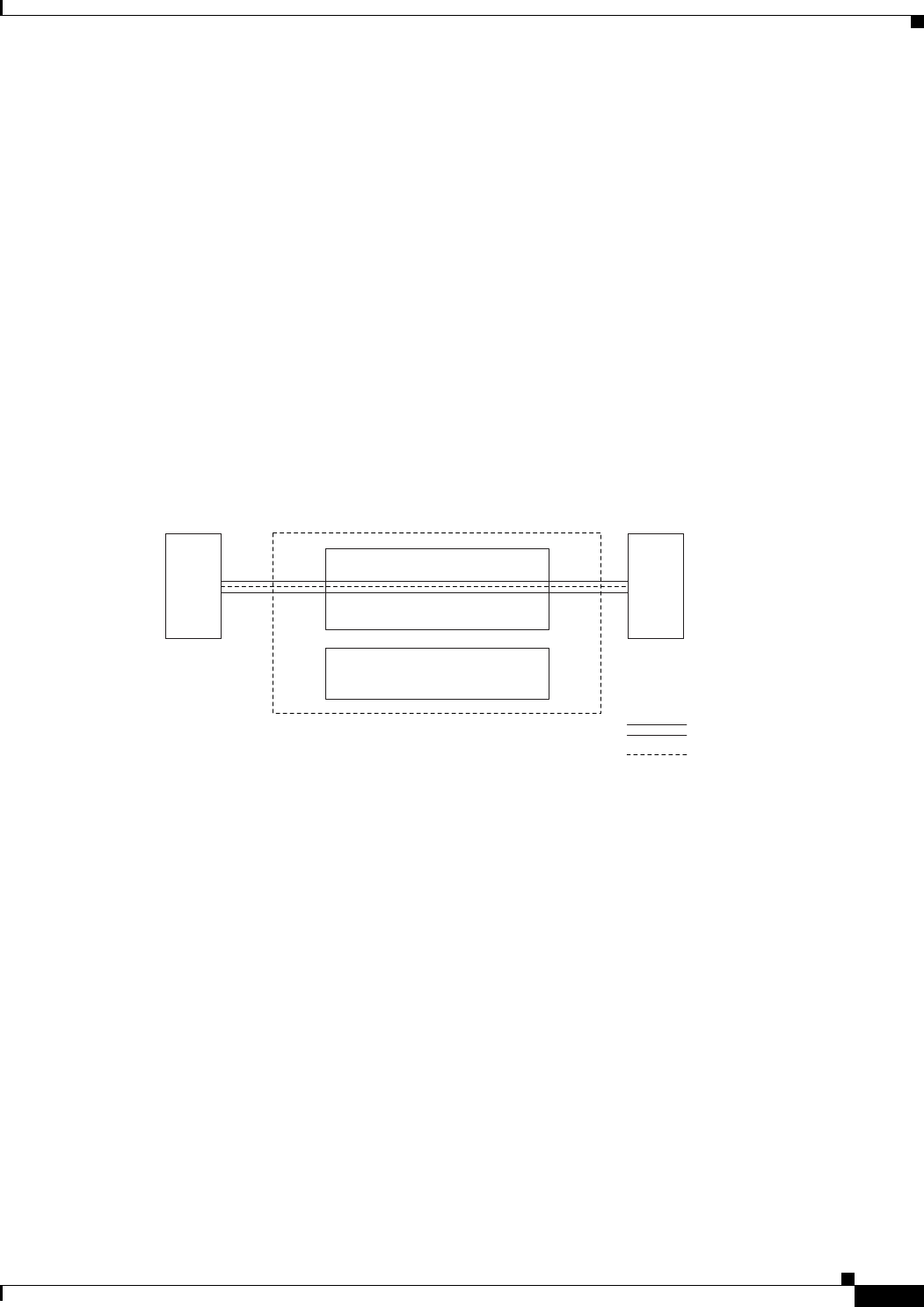
Figure 6-13 shows a VT tunnel through the XCVT and XC10G matrices. No VT1.5-mapped STSs are
used by the tunnel, which can carry 28 VT1.5s. However, the tunnel does use two STS matrix ports on
each node through which it passes.
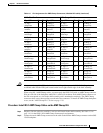
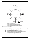
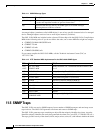
Figure 6-13 A VT1.5 tunnel
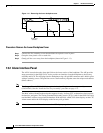
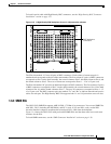
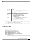
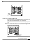
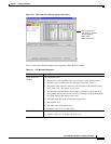
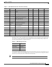
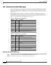
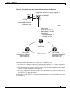
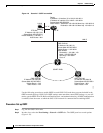
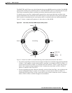
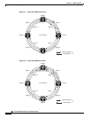
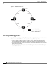
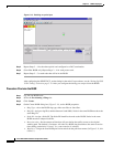
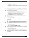
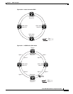
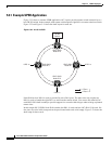
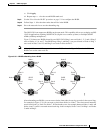
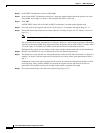
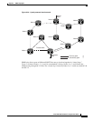
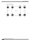
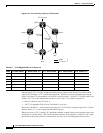
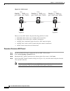
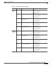
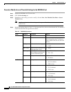
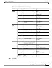
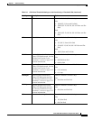
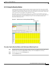
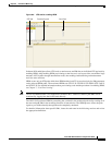
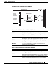
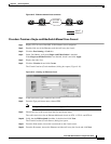
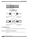
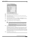
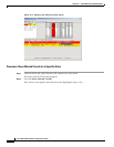
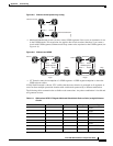
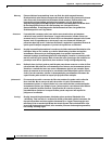
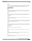
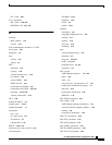
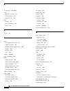
Figure 6-14 shows a six-node ONS 15454 ring with two VT tunnels. One tunnel carries VT1.5 circuits
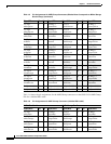
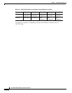
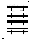
from Node 1 to Node 3. The second tunnel carries VT1.5 circuits from Node 1 to Node 4. Table 6-5
shows the VT1.5-mapped STS usage at each node in a ring based on protection scheme and use of VT
tunnels. In the Figure 6-14 example, the circuit travels west through Nodes 2, 3, and 4. Subsequently,
VT-mapped STS usage at these nodes is greater than at Nodes 5 and 6.
61850
STS Matrix
VT Tunnel
VT1.5
VT1.5 Matrix
OC
Trunk
OC
Trunk