1-35
Cisco ONS 15454 Installation and Operations Guide
November 2001
Chapter 1 Hardware Installation
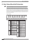
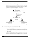
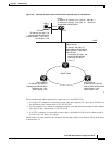
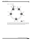
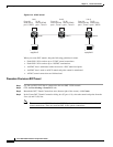
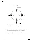
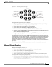
Alarm, Timing, LAN, and Craft Pin Connections
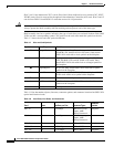
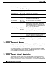
*The Cisco ONS 15454 is DCE.
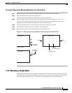
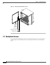
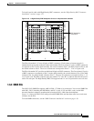
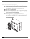
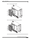
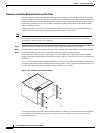
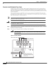
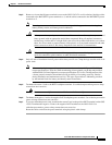
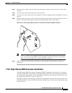
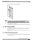
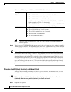
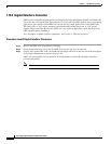
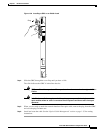
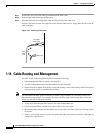
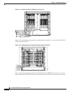
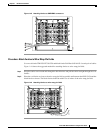
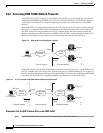
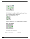
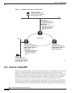
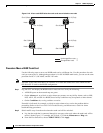
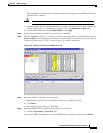
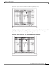
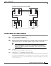
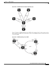
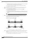
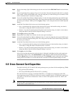
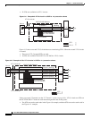
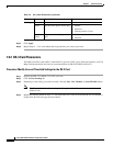
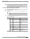
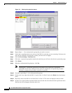
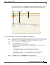
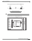
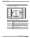
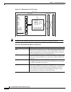
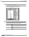
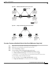
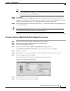
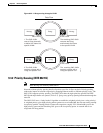
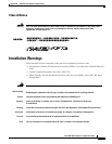
Procedure: Install LAN Wires on the Backplane
Step 1 Use #22 or #24 AWG wire.
Step 2 Wrap the wires on the appropriate wire-wrap pins according to local site practice.
Step 3 A frame ground pin is located beneath each pin field (FG2 for the LAN pin field). Wrap the ground shield
of the LAN interface cable to the frame ground pin.
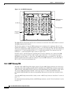
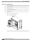
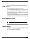
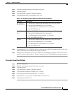
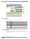
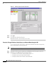
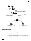
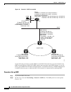
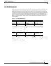
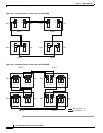
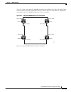
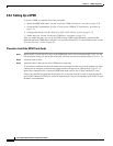
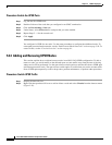
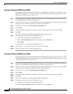
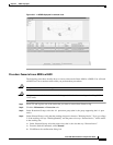
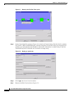
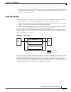
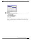
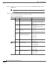
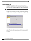
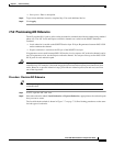
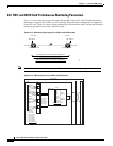
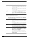
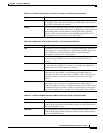
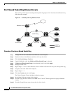
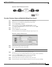
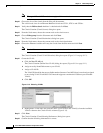
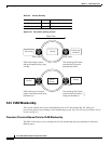
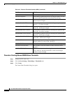
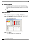
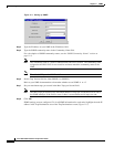
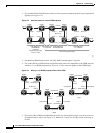
1.9.4 TL1 Craft Interface Installation
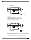
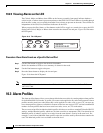
You can use the craft pins on the ONS 15454 backplane or the RS-232 port on the TCC+ faceplate to
create a VT100 emulation window to serve as a TL1 craft interface to the ONS 15454. Use a
straight-through cable to connect to the RS-232 port. Table 1-4 shows the pin assignments for the
CRAFT pin field.
Note You cannot use the craft backplane pins and the RS-232 port on the TCC+ card simultaneously.
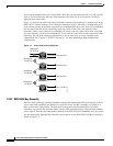
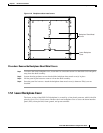
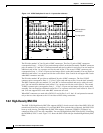
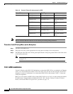
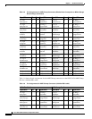
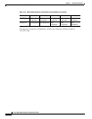
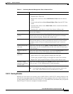
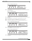
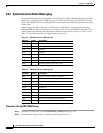
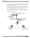
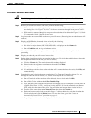
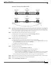
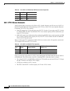
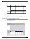
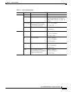
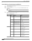
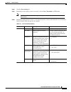
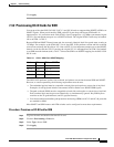
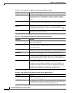
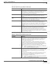
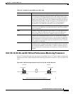
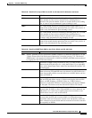
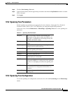
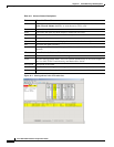
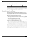
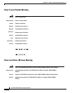
Table 1-3 LAN Pin Assignments
Pin Field Backplane Pins RJ-45 Pins
LAN 1
Connecting to data
circuit-terminating
equipment (DCE*) (a
hub or switch)
B2 1
A2 2
B1 3
A1 6
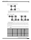
LAN 1
Connecting to data
terminal equipment
(DTE) (a
PC/workstation or
router)
B1 1
A1 2
B2 3
A2 6
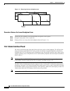
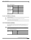
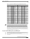
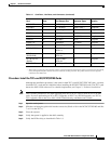
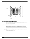
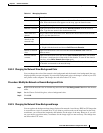
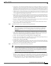
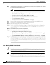
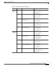
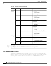
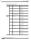
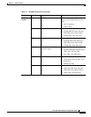
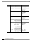
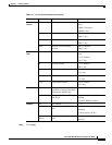
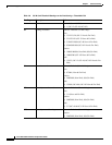
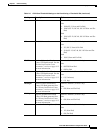
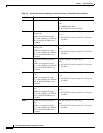
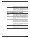
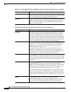
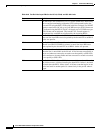
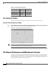
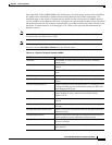
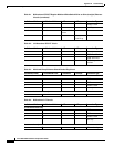
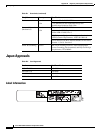
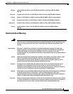
Table 1-4 Craft Interface Pin Assignments
Pin Field Contact Function
Craft A1 Receive
A2 Transmit
A3 Ground
A4 DTR