5-34
Cisco ONS 15454 Installation and Operations Guide
78-13453-01
Chapter 5 SONET Topologies
Unidirectional Path Switched Rings
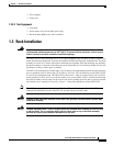
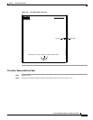
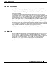
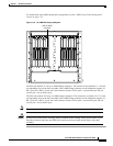
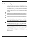
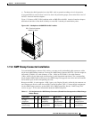
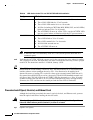
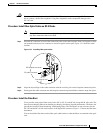
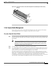
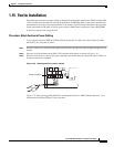
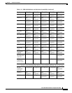
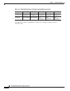
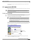
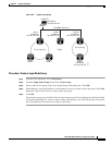
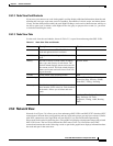
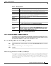
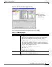
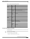
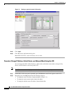
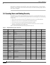
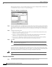
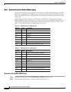
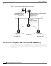
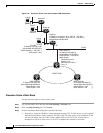
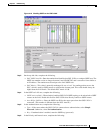
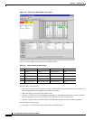
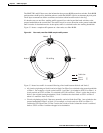
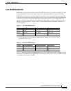
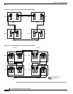
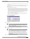
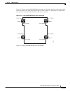
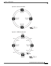
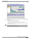
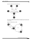
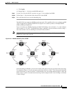
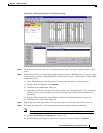
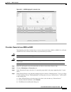
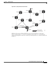
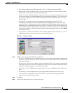
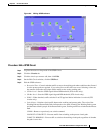
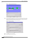
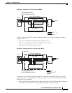
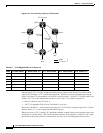
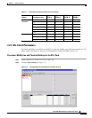
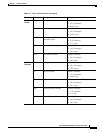
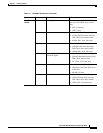
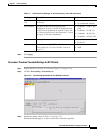
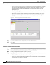
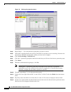
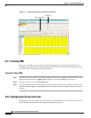
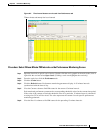
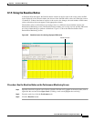
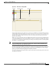
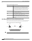
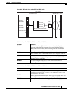
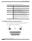
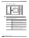
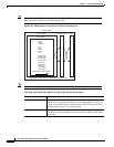
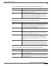
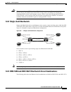
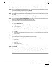
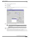
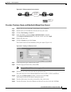
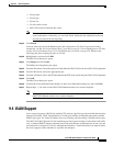
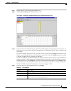
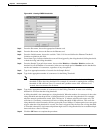
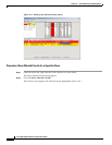
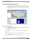
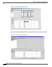
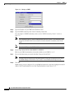
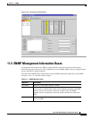
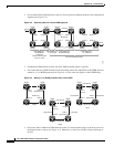
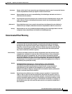
Figure 5-27 Switching UPSR circuits
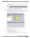
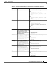
Step 4
Click Apply.
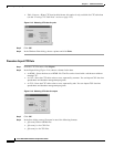
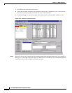
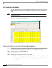
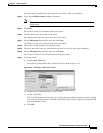
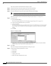
Step 5 When the confirmation dialog box appears, click OK to confirm the protection switching. The column
under Switch State changes to your chosen level of protection.
Step 6 Click Close after Switch State changes.
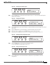
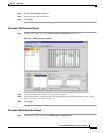
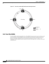
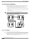
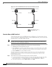
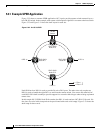
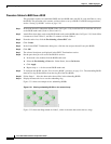
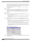
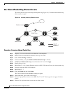
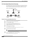
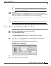
Procedure: Add a UPSR Node
Note You can add only one node at a time. Perform these steps onsite and not from a remote location.
Step 1 Log into CTC and display the UPSR nodes in network view. Verify the following:
• All UPSR spans on the network map are green.
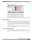
• No critical or major alarms (LOF, LOS, ASP, ASL) are displayed on the Alarms tab.
• On the Conditions tab, no UPSR switches are active.
• At each physical UPSR node, all fibers are securely connected to the appropriate ports.
If trouble is indicated, for example, a critical or major alarm exists, resolve the problem before
proceeding.
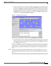
Step 2 At the node that will be added to the UPSR:
• Verify that the OC-N cards are installed and fiber is available to connect to the other nodes.
• Run test traffic through the cards that will connect to the UPSR.
• Use the “Setting Up a UPSR” section on page 5-30 to provision the new node.
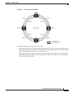
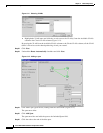
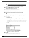
Step 3 Log into a node that will directly connect to the new node.
Step 4 Use the “Switch UPSR Traffic” procedure on page 5-32 to initiate a FORCE switch to switch traffic
away from the span that will connect to the new node.
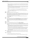
Caution Traffic is not protected during a protection switch.
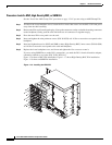
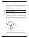
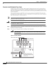
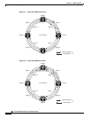
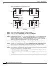
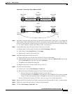
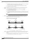
Step 5 Two nodes will connect directly to the new node; remove their fiber connections:
a. Remove the east fiber connection from the node that will connect to the west port of the new node.