1-32
Cisco ONS 15454 Installation and Operations Guide
November 2001
Chapter 1 Hardware Installation
Alarm, Timing, LAN, and Craft Pin Connections
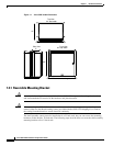
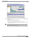
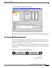
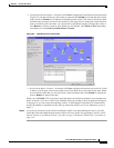
1.9 Alarm, Timing, LAN, and Craft Pin Connections
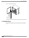
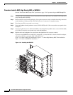
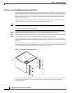
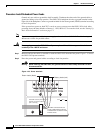
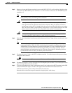
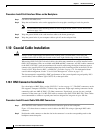
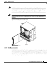
Caution Always use the supplied ESD wristband when working with a powered ONS 15454. Plug the
wristband cable into the ESD jack located on the lower-right outside edge of the shelf assembly.
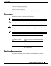
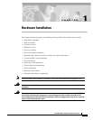
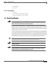
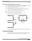
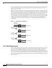
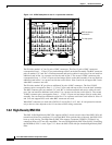
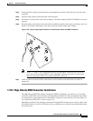
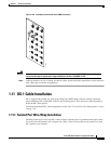
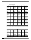
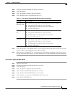
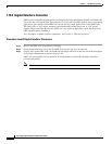
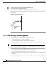
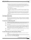
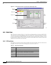
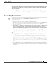
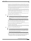
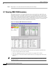
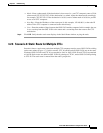
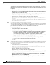
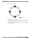
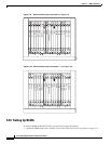
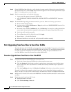
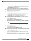
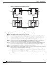
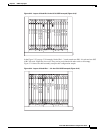
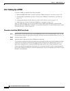
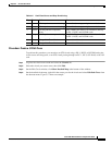
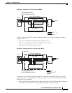
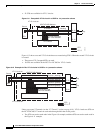
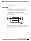
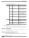
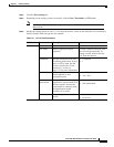
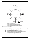
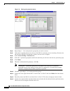
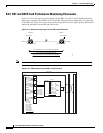
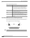
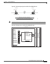
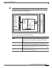
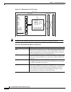
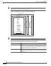
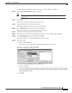
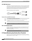
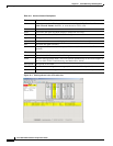
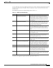
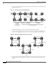
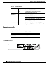
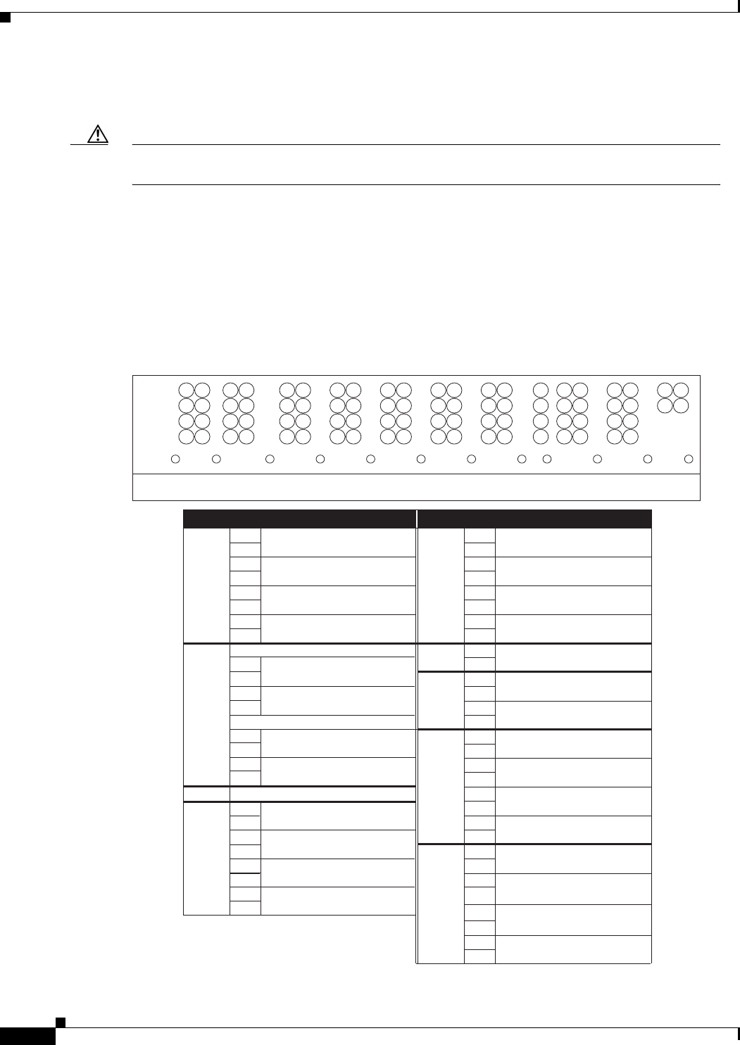
The ONS 15454 has a backplane pin field located at the bottom of the backplane. The backplane pin field
provides 0.045 square inch wire-wrap pins for enabling external alarms, timing input and output, and
craft interface terminals. This section describes the backplane pin field and the pin assignments for the
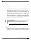
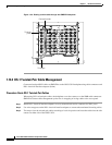
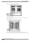
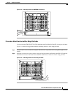
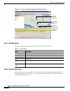
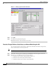
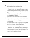
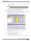
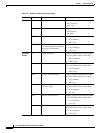
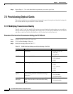
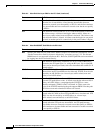
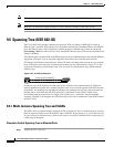
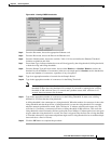
field. Figure 1-24 shows the wire-wrap pins on the backplane pin field. Beneath each wire-wrap pin is a
frame ground pin. Frame ground pins are labeled FG1, FG2, FG3, etc. Install the ground shield of the
cables connected to the backplane to the ground pin that corresponds to the pin field used. Figure 1-24
shows pinouts for the ONS 15454.
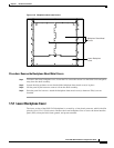
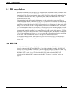
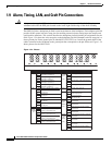
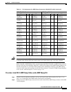
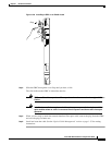
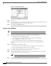
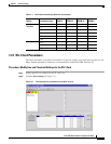
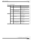
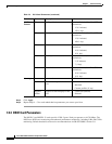
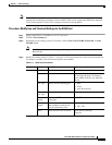
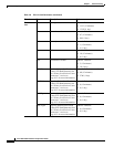
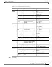
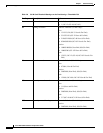
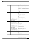
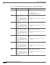
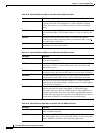
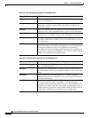
Figure 1-24 Pinouts
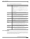
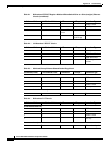
Field Pin Function Field Pin Function
BITS A1 BITS Output 2 negative (-)
ENVIR
ALARMS
OUT
N/O
A1 Normally open output pair number 1
B1 BITS Output 2 positive (+) B1
A2 BITS Input 2 negative (-) A2 Normally open output pair number 2
B2 BITS Input 2 positive (+) B2
A3 BITS Output 1 negative (-) A3 Normally open output pair number 3
B3 BITS Output 1 positive (+) B3
A4 BITS Input 1 negative (-) A4 Normally open output pair number 4
B4 BITS Input 1 positive (+) B4
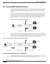
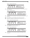
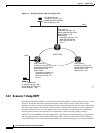
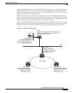
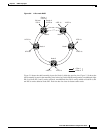
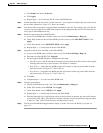
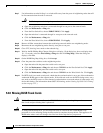
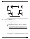
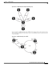
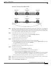
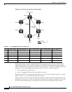
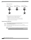
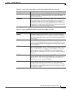
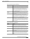
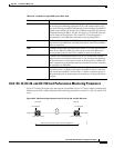
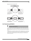
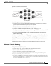
LAN 1 Connecting to a Router, Hub, or Switch ACO A1 Normally open ACO pair
A1 B1
B1 CRAFT A1 Receive (PC pin #2)
A2 A2 Transmit (PC pin #3)
LAN 2
B2 A3 Ground (PC pin #5)
A4 DTR (PC pin #4)
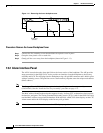
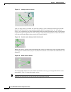
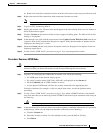
LOCAL
ALARMS
AUD
(Audible)
N/O
N/O
A1 Alarm output pair number 1: Remote
audible alarm.
B1 B1
ENVIR
ALARMS
IN
A2 Alarm output pair number 2: Critical
audible alarm.
B2
A3 Alarm output pair number 3: Major
audible alarm.
A1 B3
B1 A4 Alarm output pair number 4: Minor
audible alarm.
A2 B4
B2
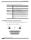
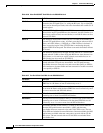
LOCAL
ALARMS
VIS
(Visual)
A1 Alarm output pair number 1: Remote
visual alarm.
A3 B1
A2 Alarm output pair number 2: Critical
visual alarm.
B2
A3 Alarm output pair number 3: Major
visual alarm.
B3
A4 Alarm output pair number 4: Minor
visual alarm.
B4
Not Used
A1
A2
B3
A4
B4
RJ-45 pin 2
RJ-45 pin 1
RJ-45 pin 2
RJ-45 pin 1
RJ-45 pin 6
Alarm input pair number 1: Reports
closure on connected wires.
Alarm input pair number 2: Reports
closure on connected wires.
Alarm input pair number 3: Reports
closure on connected wires.
Alarm input pair number 4: Reports
closure on connected wires.
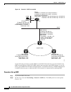
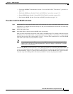
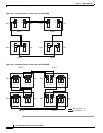
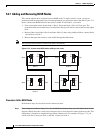
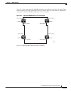
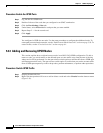
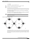
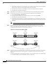
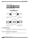
Connecting to a PC or Workstation
RJ-45 pin 3
B2
RJ-45 pin 3
RJ-45 pin 6
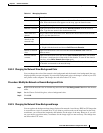
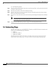
TBOS
AUDVIS
FG12FG11FG10FG9FG8FG7FG6FG5FG4FG3FG2
BITS LAN
FG1
111111111111
2222222222
3333333333
4444444444
2
3
4
2
ABABAABABABABABABABA B
LOCAL ALARMSCRAFTMODEM X . 25 ACO ENVIR ALARMS
OUTIN
38533