A-5
Cisco ONS 15454 Installation and Operations Guide
November 2001
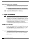
Appendix A Circuit Routing
Manual Circuit Routing
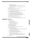
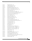
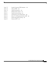
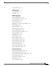
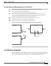
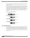
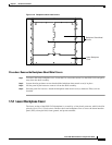
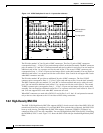
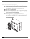
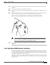
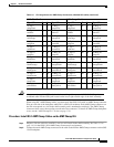
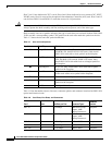
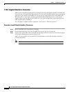
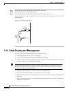
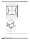
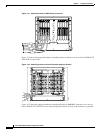
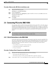
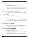
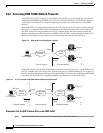
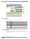
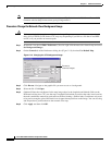
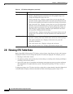
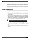
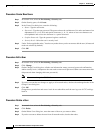
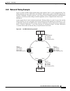
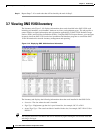
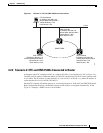
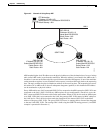
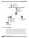
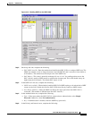
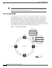
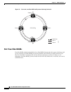
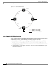
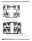
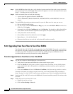
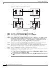
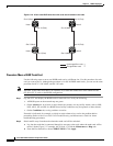
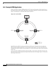
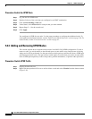
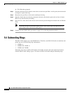
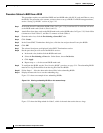
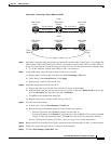
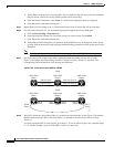
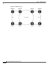
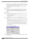
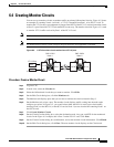
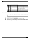
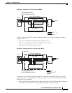
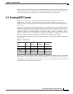
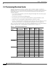
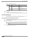
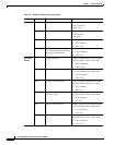
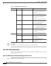
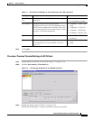
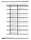
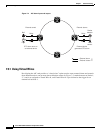
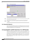
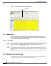
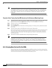
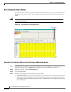
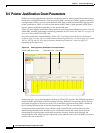
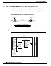
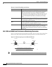
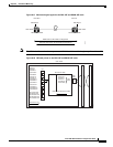
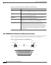
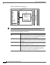
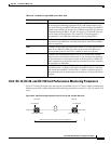
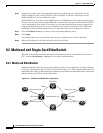
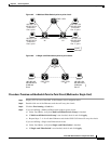
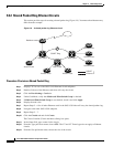
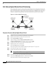
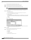
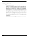
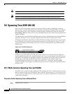
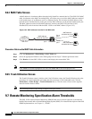
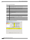
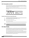
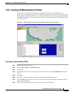
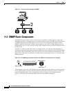
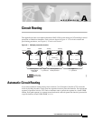
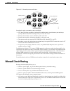
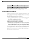
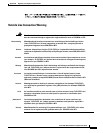
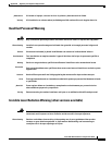
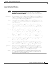
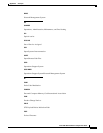
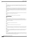
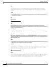
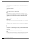
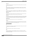
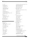
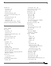
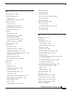
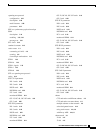
Figure A-5 Ethernet shared packet ring routing
•
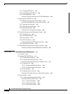
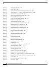
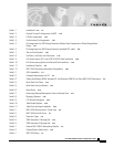
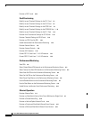
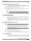
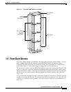
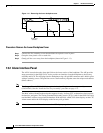
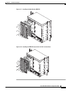
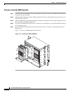
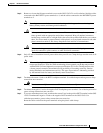
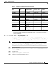
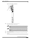
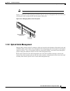
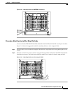
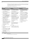
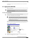
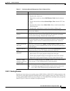
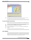
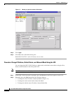
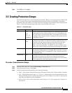
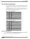
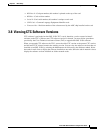
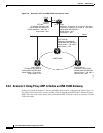
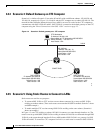
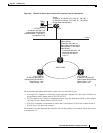
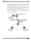
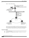
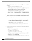
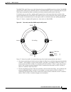
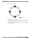
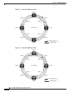
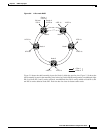
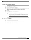
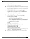
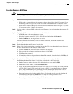
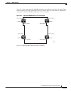
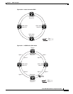
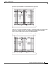
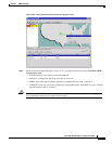
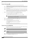
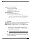
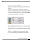
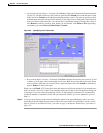
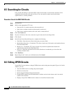
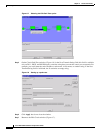
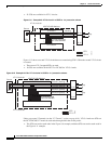
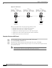
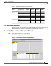
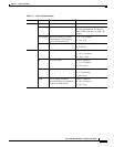
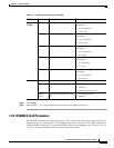
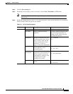
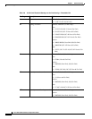
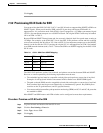
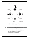
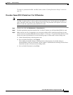
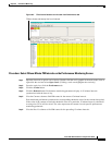
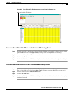
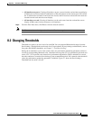
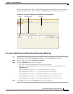
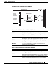
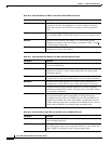
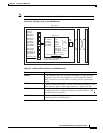
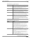
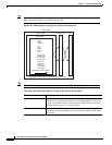
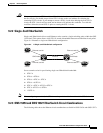
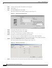
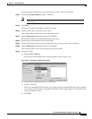
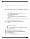
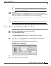
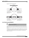
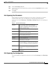
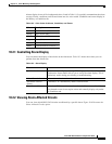
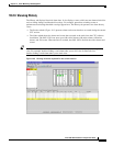
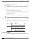
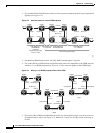
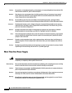
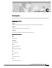
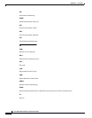
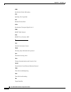
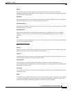
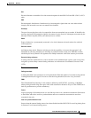
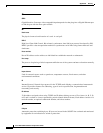
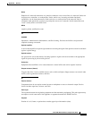
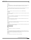
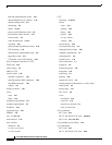
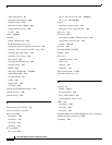
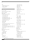
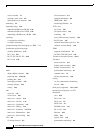
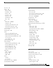
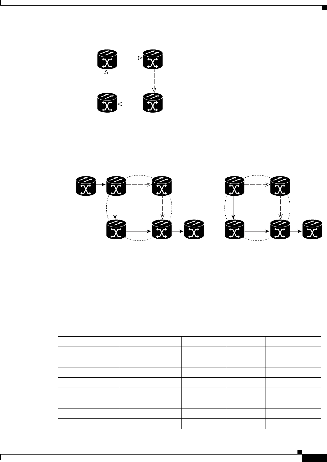
Multicard EtherSwitch circuits can have virtual UPSR segments if the source or destination is not
in the UPSR domain. This restriction also applies after circuit creation; therefore if you create a
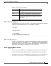
circuit with UPSR segments, Ethernet node drops cannot exist anywhere on the UPSR segment (see
Figure A-6).
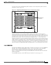
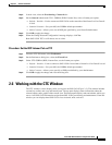
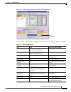
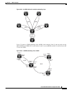
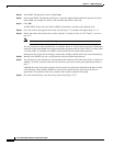
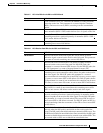
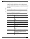
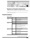
Figure A-6 Ethernet and UPSR
• VT Tunnels cannot be an endpoint of a UPSR segment. A UPSR segment endpoint is where the
UPSR selector resides.
If Fully Path Protected is chosen, CTC verifies that the route selection is protected at all segments. A
route can have multiple protection domains with each domain protected by a different mechanism.
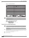
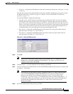
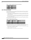
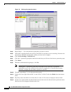
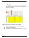
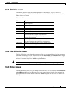
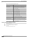
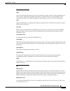
The following tables summarize the available node connections. Any other combination is invalid and
will generate an error.
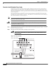
55405
Ethernet source
Ethernet destination
Node 4Node 3
Node 1 Node 2
55406
UPSR Segment
Legal
Node 8Node 7
Node 5Node 2
Node 11 Node 11
Node 6
Source
Drop
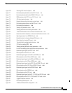
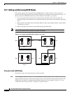
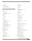
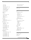
UPSR Segment
Illegal
Node 8Node 7
Node 5 Node 6
Source
Drop
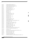
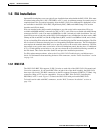
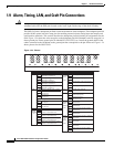
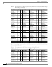
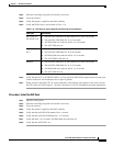
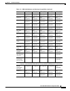
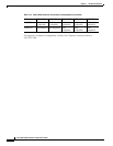
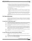
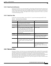
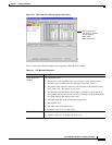
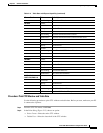
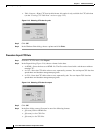
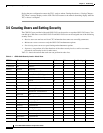
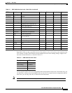
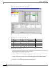
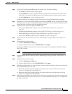
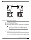
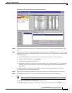
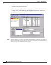
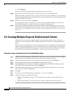
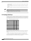
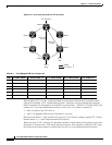
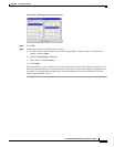
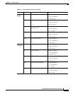
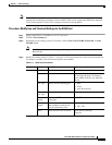
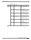
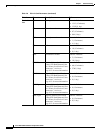
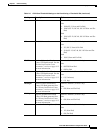
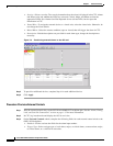
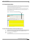
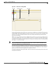
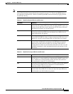
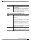
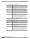
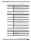
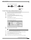
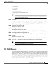
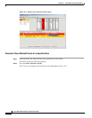
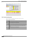
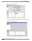
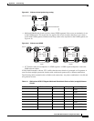
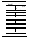
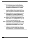
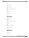
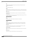
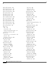
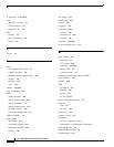
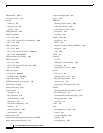
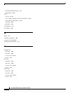
Table A-1 Bidirectional STS/VT/Regular Multicard EtherSwitch/Point-to-Point (straight) Ethernet
Circuits
# of Inbound Links # of Outbound Links # of Sources # of Drops Connection Type
- 2 1 - UPSR
2 - - 1 UPSR
21--UPSR
12--UPSR
1 - - 2 UPSR
- 1 2 - UPSR
22--Double UPSR
2 - - 2 Double UPSR