


Service Manual Repair procedures 67
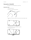
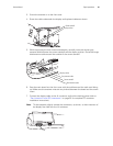
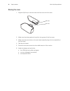
3. Screw the antenna on to the front case.
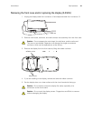
4. Route the cable underneath the display and keyboard cables as shown.
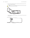
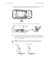
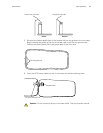
5. While supporting the main board subassembly, carefully route the shorter gray
antenna cable between the screw standoff and the display cushion. Route the longer
black antenna cable around the outside of the screw standoff.
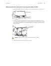
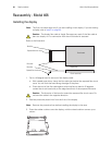
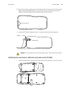
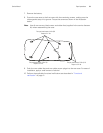
6. Seat the main board into the front case with the subframe and the radio card facing
up. Make sure the antenna wires are not pinched between the board and the screw
insert.
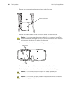
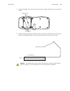
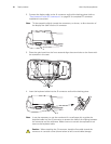
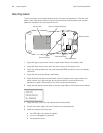
7. Connect the display cable to the J4 connector and lock the latching piece (refer to
“Zero Insertion Force (ZIF) connectors” on page 32 for complete ZIF connector
installation instructions.)
Note
Tilt the assembly slightly toward the connectors, as shown, to allow insertion of
the display flex cable into the J4 connector.
Screw standoff
Display cushion
Display cushion
Gray antenna cable
Screw standoff
Black antenna cable
J4