


28 Troubleshooting Welch Allyn Micropaq Monitor
Lines in the display. Check for display circuit damage caused
by improper display installation. Solder
connections on the ECG or SpO
2
connectors may damage the display
circuit.
Replace the display assembly. See "Removing the
front case and/or replacing the display (5 GHz)" on
page 39 (model 408) or "Removing the front case
and/or replacing the display (5 GHz)" on page 61
(model 406).
SpO
2
is not working. Bad connection to the SpO
2
board.
Possible error code OXB87 on the display.
Check connections at the SpO
2
board assembly.
Bad SpO
2
flex cable connection to the
main board at connector J8.
Check the SpO
2
flex cable connection at J8: unlock
the ZIF connector, reseat the flex cable, and then
relock the connector.
SpO
2
sensor has no LED. Check the ground connection to the main board at
connector J9. On Nellcor models, verify the dip
switch is set to 0110.
Broken SpO
2
flex cable solder
connection.
Check for fractured solder joints on the SpO
2
connector (often caused by dropping the monitor).
Send the monitor to Welch Allyn factory service for
repair.
Broken SpO
2
flex cable. Replace the rear case assembly. See "Removing the
rear case" on page 38.
SpO
2
external connector is damaged. Replace the rear case assembly. See "Removing the
rear case" on page 38.
Bad SpO
2
assembly. Send to Welch Allyn factory service for repair.
ECG “LEADS OFF”
message when ECG
leads are connected.
Broken ECG flex cable solder connection. Check for fractured solder joints on the ECG
connector (often caused by dropping the monitor).
Send to Welch Allyn factory service for repair.
ECG is not working. Bad ECG connection. Check the ECG connection to the main board at
connector J1: unlock the ZIF connector, reseat the
flex cable, and then relock the connector.
Broken ECG flex cable solder connection. Check for fractured solder joints on the ECG
connector (often caused by dropping the monitor).
Repair solder joints and retest the monitor.
Broken ECG flex cable. Replace the appropriate rear case assembly. See
"Removing the rear case" on page 38 (model 408) or
"Remove the ECG flex cable from connector J1 on
the main board. The rear case may now be
replaced." on page 60 (model 406).
ECG external connector is damaged. Replace the appropriate rear case assembly. See
"Removing the rear case" on page 38 (model 408) or
"Remove the ECG flex cable from connector J1 on
the main board. The rear case may now be
replaced." on page 60 (model 406).
Bad main board. Send the monitor to Welch Allyn factory service for
repair.
No power or power
intermittent.
Broken battery connector. Send the monitor to Welch Allyn factory service for
repair.
The monitor causes
rf/emi interference.
Nylon washers and metal washers are
incorrectly installed on the SpO
2
board/
shield.
Install nylon washers in the correct locations
according to the instructions in "Installing the SpO
2
shield" on page 55.
SpO
2
shield is not correctly installed. Check that the SpO
2
shield is installed according to
the instructions in "Installing the SpO
2
shield" on
page 55.
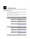
Symptom Possible cause Possible corrective action