


13
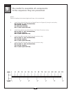
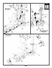
Be careful to assemble all components
in the sequence they are presented.
mm
Inch
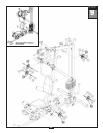
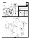
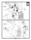
STEP
NOTE:
Leave all pulley bolts hand tight until step 15
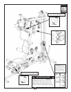
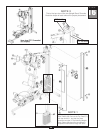
A. Route Cable (86) up
and through the bottom of 45 Degree Double Pulley Holder (CB). Install
Pulley (B5) using:
One 51 (3/8” x 1 3/4” hex head bolt)
Two 74 (3/8” washer)
One 71 (3/8” nylon lock nut)
B. Route Cable (86) down
, around pre-installed Pulley (B6). Remove and re-install pulley as needed.
Route Cable (86) forward and through the opening in Angled Support Frame (D).
Route Cable (86) under
pre-installed Pulley (B7). Remove and re-install pulley as needed.
Insert Cable (86) through Leg Extension Arm (X) and install Pulley (B8) using:
One 51 (3/8” x 1 3/4” hex head bolt)
Two 74 (3/8” washer)
One 71 (3/8” nylon lock nut)
E. Attach Short Cable (87) to Main Base Frame (A) as shown using:
One 53 (3/8” x 3” hex head bolt)
T
wo 74 (3/8” washer)
One 71 (3/8” nylon lock nut)
F. Attach the other end of Cable (87) to the hook on the bottom of Pulley Holder (CD) as shown.
34
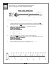
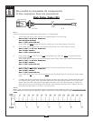
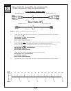
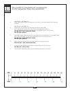
Small Ball Stop End
Small Ball Stop End
5080 mm
16’ 8”
Low Pulley Cable (86)
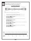
Short Cable (87)
Stamped Eye End
Stamped Eye End
757 mm
2’ 6”