


10
Be careful to assemble all components
in the sequence they are presented.
28
STEP
Note:
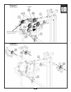
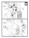
Leave all pulley bolts hand tight until step 15 is completed.
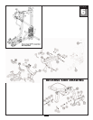
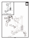
A. Begin at the high pulley station. Route the metal ball end of the High Pulley Cable (85) up
and
through the opening where Pulley (A1) will be installed. Route the metal ball end under the
Bi-Angular Bars (J) and then down
through the next opening where Pulley (A2) will be installed.
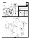
B. Install Pulley (A1) under Cable (85) and into Top Frame (E) as shown using:
One 52 (3/8” x 2 3/4” hex head bolt)
T
wo 84 (nylon bushing)
One 71 (3/8” nylon lock nut)
C. Install Pulley (A2) under Cable (85) and into Top Frame (E) as shown using:
One 52 (3/8” x 2 3/4” hex head bolt)
T
wo 84 (nylon bushing)
One 71 (3/8” nylon lock nut)
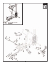
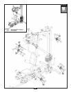
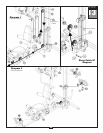
D. Route Cable (85) over
the top and around pre-installed Pulley (A3) as shown.
Route Cable (85) around Pulley (A4) and install Pulley (A4) into Angled Support Frame (D) using:
One 52 (3/8” x 2 3/4” hex head bolt)
Two 84 (nylon bushing)
One 71 (3/8” nylon lock nut)
E. Route Cable (85) between Pulley (A3) and pre-installed Pulley (A5).
Route Cable (85) ar
ound Pulley (A5) and back through Angled Support Frame (D).
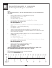
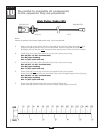
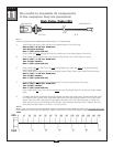
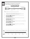
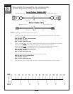
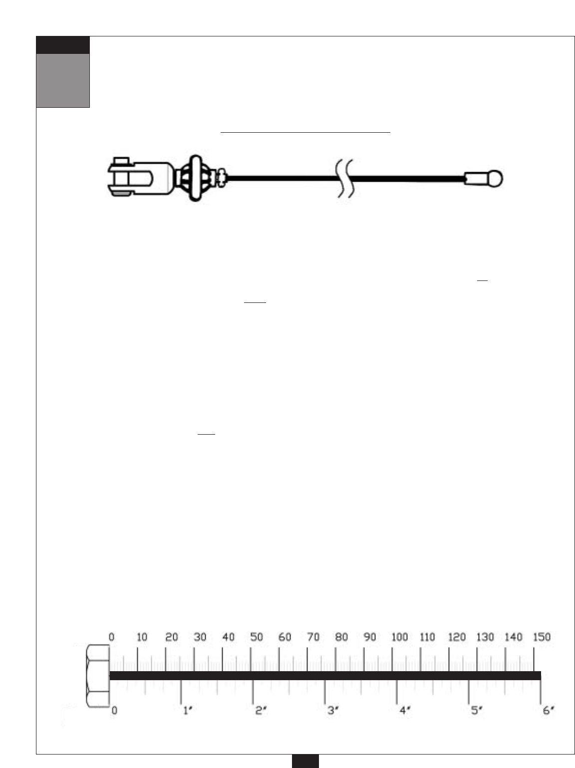
High Pulley Cable (85)
Ball Stop End
Metal Ball End
5110 mm
16’ 9”
mm
Inch