


Be careful to assemble all components
in the sequence they are presented.
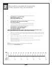
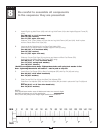
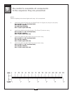
mm
Inch
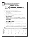
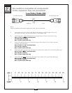
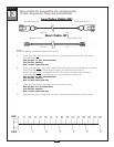
Ball Stop End
Metal Ball End
5110 mm 16’ 9”
11
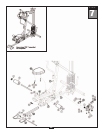
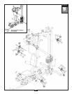
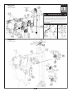
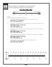
Note:
Leave all pulley bolts hand tight until step 15 is completed.
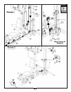
A. Install Pulley (A6) under Cable (85) and into Angled Support Frame (D) using:
One 52 (3/8” x 2 3/4” hex head bolt)
Two 84 (nylon bushing)
One 71 (3/8” nylon lock nut)
Route Cable (85) down
through the small arm sticking out of the Angled Support Frame (D).
B. Route Cable (85) through the top of the Double Pulley Holder (CA). Install Pulley (A7) using:
One 51 (3/8” x 1 3/4” hex head bolt)
T
wo 74 (3/8” washer)
One 71 (3/8” nylon lock nut)
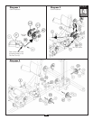
C. Route Cable (85) up
to Top Frame (E), over pre-installed Pulley (A8), and down to 45 Degree Double
Pulley Holder (CB).
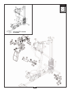
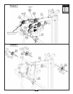
Route Cable (85) through the top of the 45 Degree Double Pulley Holder (CB). Install Pulley (A9) using:
One 51 (3/8” x 1 3/4” hex head bolt)
T
wo 74 (3/8” washer)
One 71 (3/8” nylon lock nut)
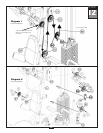
C. Route Cable (85) up
through the Top Weight Stack Frame (G). Install Pulley (A10) using:
One 51 (3/8” x 1 3/4” hex head bolt)
Two 74 (3/8” washer)
One 71 (3/8” nylon lock nut)
Route Cable (85) up
over Pulley (A10) and down through Top Weight Stack Frame (G) and toward weight
stack.
D. The Metal Ball End of Cable (85) should be hanging just above the weight stack. Remove Allen Bolt (102)
from Selector Rod Top Bolt (103), slide Metal Ball End of Cable (85) through Selector Rod Top Bolt (103).
Attach Cable End Shaft (100) and securely tighten Allen Bolt (101). Pull Cable (85) tight, so Cable End
Shaft (100) fits securely inside Selector Rod Top Bolt (103). Reinstall Allen Bolt (102) in Selector Rod Top
Bolt (103) and tighten Nylon Lock Nut (71) to hold in place.
NOTE:
Make sur
e the Selector Rod Top Bolt (103) is threaded inside Selector Rod (19) at least one half
inch. Make sure Spring Lock Washer (105) is in place and wrench tighten Jam Nut (104).
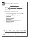
High Pulley Cable (85)
STEP
30