


6
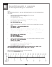
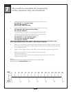
Be careful to assemble all components
in the sequence they are presented.
mm
Inch
20
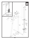
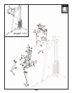
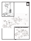
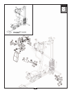
STEP
NOTE:
LEG EXTENSION FRAME (V) AND THE SEAT PAD FRAME (W) ARE PRE-ASSEMBLED AS
ONE PIECE.
A. Attach Leg Extension Frame (V) to Angled Support Frame (D) using:
Two 40 (1/2” x 3 1/4” hex head bolt)
Four 73 (1/2” washer)
T
wo 70 (1/2” nylon lock nut)
B. Attach the bottom of Leg Extension Frame (V) to Main Base Frame (A) using:
One 44 (1/2” x 5 1/2” hex head bolt)
T
wo 73 (1/2” washer)
One 70 (1/2” nylon lock nut)
C. Attach Leg Extention Arm (X) to Leg Extension Frame (V) with pr
e-installed Shaft (47) as shown
using:
Two 49 (5/16” x 1/2” round allen head bolt)
T
wo 76 (5/16” washer)
D. Tighten the two Allen Screws (34) to lock down Shaft (47) in Leg Extension Frame (V).
Attach two Convex End Caps (2) one to the top of Leg Extension Frame (V) and one to the top of
the Leg Extension Ar
m (X) as shown.
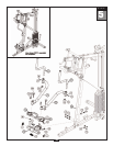
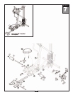
E. Attach Lock Down Hook (152) to Leg Extension Frame (V) as shown in the REVERSE SIDE
DRAWING using:
One 57 (3/8” x 2 1/2” hex head bolt)
T
wo 73 (1/2” washer)
One 153 (5/16” wide spacer)
F. Attach Leg Extension Pad Holder (Y) and 1/4” Wide Spacer (154) to Leg Extension Ar
m (X) using:
One 150 (1/2” x 4 1/2” hex head bolt)
Thr
ee 73 (1/2” washer)
One 70 (1/2” nylon lock nut)
G. Attach Leg Pads (AA) to Leg Extension Pad Holder (Y) using:
Four 61 (5/16” x 3/4” round allen head bolt)*
Four 77 (5/16” spring lock washer)
Four 76 (5/16” washer)
*
Do NOT over-tighten these bolts. Tighten these bolts until spring lock washer is flat.
Over - tightening these bolts will cause T - nuts in pads to strip out.
Note:
You should now wr
ench tighten all bolts and nuts in this step.
Do NOT re-tighten any of the pad bolts.