


12
Be careful to assemble all components
in the sequence they are presented.
mm
Inch
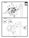
STEP
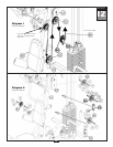
Note:
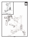
Leave all pulley bolts hand tight until step 15 is completed.
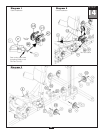
A. Insert either end of Low Pulley Cable (86) into the opening in Angled Support Frame (D),
above Back Pad (BB), and pull entir
e length of Cable (86) through.
B. Install Pulley (B1), under
Cable (86) and into Angled Support Frame (D) as shown using:
One 57 (3/8” x 2 1/2” hex head bolt)
Two 84 (nylon bushing)
One 71 (3/8” nylon lock nut)
C. Route Cable (86) through the top of the 90 Degr
ee Pulley Holder (CC) and hold in place by
installing Pulley (B2) using:
One 51 (3/8” x 1 3/4” hex head bolt)
T
wo 74 (3/8” washer)
One 71 (3/8” nylon lock nut)
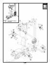
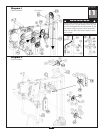
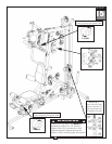
D. Route Cable (86) up
and through the bottom of Double Pulley Holder (CA). Install Pulley (B3) using:
One 51 (3/8” x 1 3/4” hex head bolt)
Two 74 (3/8” washer)
One 71 (3/8” nylon lock nut)
E. Route Cable (86) down
and through the Single Pulley Holder (CD). Install Pulley (B4) using:
One 51 (3/8” x 1 3/4” hex head bolt)
Two 74 (3/8” washer)
One 71 (3/8” nylon lock nut)
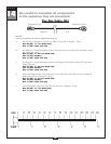
32
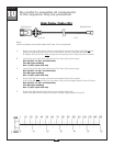
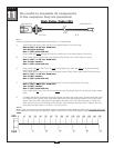
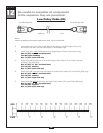
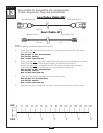
Small Ball Stop End
Small Ball Stop End
5080 mm 16’ 8”
Low Pulley Cable (86)