


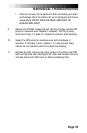

Page 63
5. Remove the drive chain.
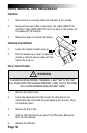
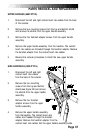
6. Remove the sprocket and the other small parts from the left side of
the hub assembly (see Figure 18).
7. Slide the drive shaft to the right, out of the hub assembly. If you
remove the right-hand clutch sprocket from the drive shaft, do not
confuse it with the left-hand clutch sprocket.
8. Loosen and remove the two remaining bolts and nuts that hold the
hub assembly to the frame. Remove the hub assembly.
9. Inspect the drive shaft, the bushings, the thrust washers, and
clutch sprockets for excessive wear or pitting. Replace worn-out
components.
10. To reinstall the hub assembly, carefully reverse the disassembly
procedures. Be sure that the right- and left-hand clutch sprockets are
positioned correctly; the wide shoulder of the sprocket should be
facing away from the hub on both sides.
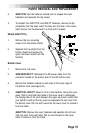
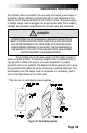
11. Chain Tension. The drive shaft is mounted in an eccentric hub.
Rotate the hub so the marked hole is in the 12 o’clock position, lining
up four holes in the hub with the four holes in the frame. Use this hub
position when reinstalling the drive chain since the distance between
the drive and transmission shafts is at a minimum. The hub is in the
proper position when the drive chain has a total of 1 to 1-1/2" (2.5 to
4.0 cm) of play at the slackest point. As the drive chain stretches with
use, increase the chain tension (and the distance between the two
shafts) by rotating the hub counterclockwise (see Figure 26). The
distance between the two shafts is greatest when the marked hole in
the hub is at the 8 o’clock position.
12. Reinstall the covers.
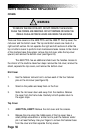
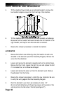
PARTS REMOVAL AND REPLACEMENT