


7
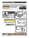
Assembly requires two persons. Set the INCLINE TRAINER in a cleared area and remove all packing materials.
Do not dispose of the packing materials until assembly is completed. Assembly can be completed using the
included hex keys.
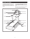
Note: The underside of the INCLINE TRAINER walking belt is coated with high-performance lubricant. During
s
hipping, a small amount of lubricant may be transferred to the top of the walking belt or the shipping carton. This
is a normal condition and does not affect INCLINE TRAINER performance. If there is lubricant on top of the walk-
ing belt, simply wipe off the lubricant with a soft cloth and a mild, non-abrasive cleaner.
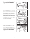
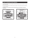
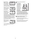
3. Connect the Right Upright Wire Harness (105), the TV
Cable (33), and the Left Upright Wire Harness (131) in
the indicated locations. The connectors should slide
together easily and snap into place.
If they do not, turn
the connectors and try again. IF THE CONNECTORS
ARE NOT CONNECTED PROPERLY, THE CONSOLE
MAY BE DAMAGED WHEN THE POWER IS TURNED
ON.
Push all of the excess wire up into the Uprights (96,
107). Make sure that all wires are fully connected.
Note: Regardless of which console your INCLINE
TRAINER has, connect all wires so that the console
can later be upgraded if desired.
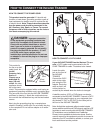
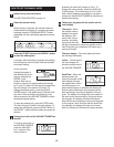
See step 1. Whilst a second person holds the Uprights
(96, 107), remove the Upright Bolts (106). Slide the
Uprights fully onto the Base Frame (52). Be careful to
avoid pinching your hands or the wires.
2. Whilst a second person holds the Handrail (94) near the
Uprights (96, 107), feed the wires in both sides of the
Handrail down into the Uprights. Pull the ends of the
wires out of the lower ends of the Uprights and remove
the wire ties from the ends of the wires.
Finger tighten four Handrail Bolts (93) into the Handrail
(94) and the Uprights (96, 107) as shown. Be careful to
avoid pinching the wires in the Handrail.
Note: The Accessory Holder (142) and the Cup Holder
(10) are replaceable. If these parts become dislodged
from the Console (89), press them back into place.
94
107
96
93
142
89
10
93
Wires
2
HOW TO SET UP THE INCLINE TRAINER
107
96
105
33
131
3
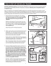
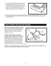
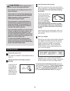
1. Slide the Right and Left Uprights (96, 107) onto the
brackets near the front of the Base Frame (52).
Make
sure that the Uprights are on the correct sides; the
indicated holes must be facing the INCLINE
TRAINER.
Raise the Left Upright (107) until the lower hole in the
front of the Left Upright is aligned with the upper hole in
the bracket as shown. Thread an Upright Bolt (106) into
the Left Upright and the bracket.
Do not fully tighten
the Upright Bolt yet.
Repeat this step with the Right Upright (96).
107
52
52
Holes
106
106
96
1