


14
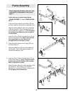
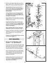
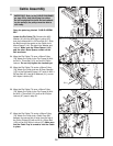
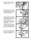
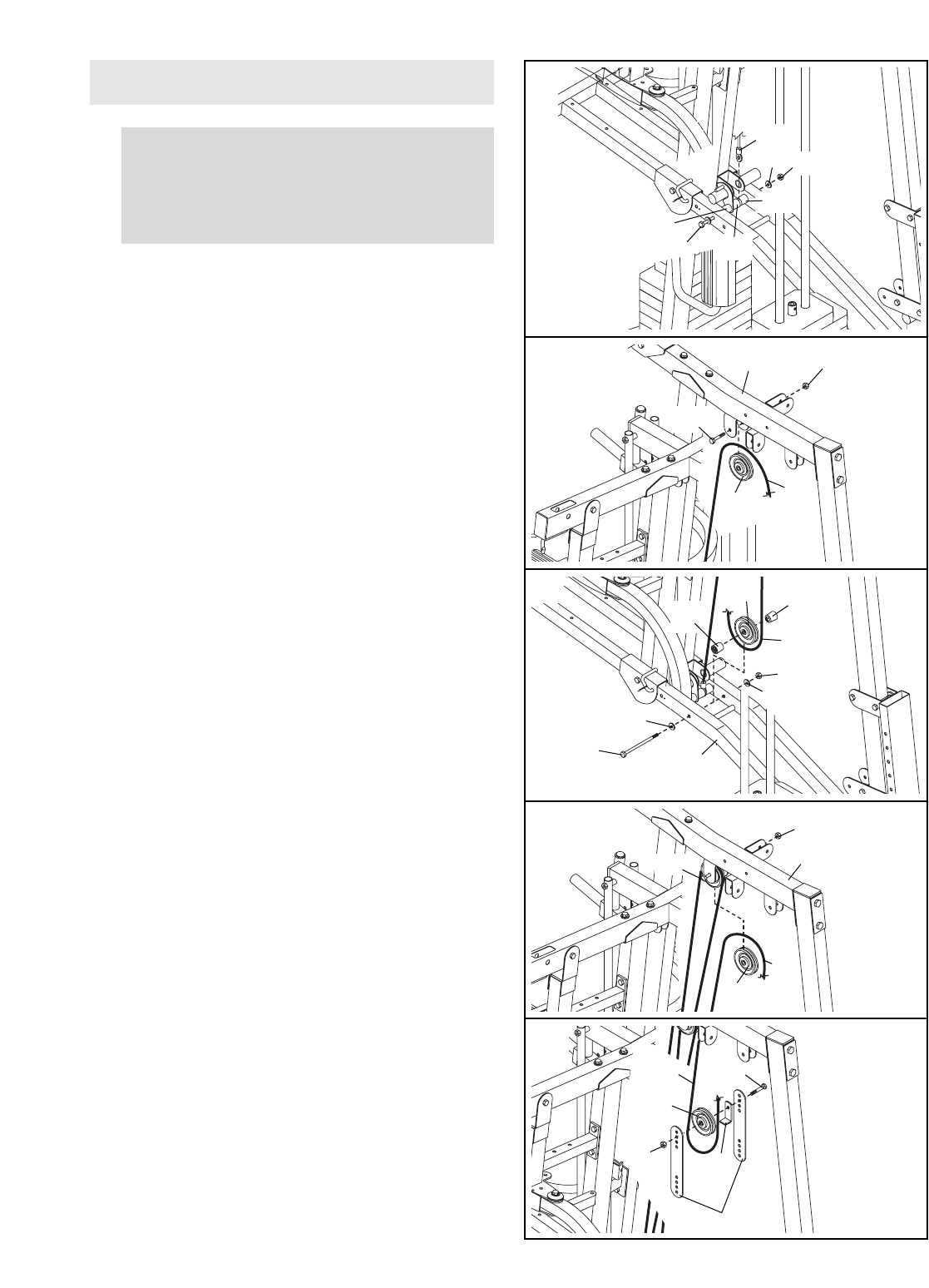
23.
Open the parts bag labeled “CABLE ASSEM-
BLY.”
Locate the Dip Cable (74). Remove the M10
Washer (91) and the M10 Nylon Locknut (87)
from the indicated M10 x 207mm Bolt (61). Slide
the Bolt through the eyelet on the Cable and a
40mm Spacer (141). Re-attach the Washer and
Locknut. Make sure the 22mm Spacer (144)
and the other 40mm Spacer remain on the
Bolt as shown.
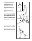
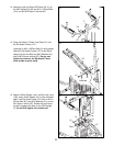
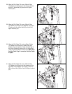
24. Wrap the Dip Cable (74) over a 90mm Pulley
(78). Attach the Pulley to the Top Frame (6) with
an M10 x 75mm Bolt (101) and an M10 Nylon
Locknut. Do not fully tighten the Locknut yet.
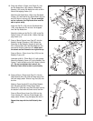
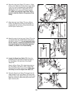
25. Wrap the Dip Cable (74) under a 90mm Pulley
(78). Attach the Pulley and two 42.5mm Spacers
(137) to the Dip Assist Frame (127) with an M10 x
207mm Bolt (61), two M10 Washers (91), and an
M10 Nylon Locknut (87).
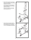
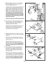
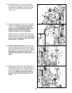
26. Wrap the Dip Cable (74) over a 90mm Pulley
(78). Attach the Pulley to the Top Frame (6) with
the M10 x 75mm Bolt (101) and an M10 Nylon
Locknut (87) used in step 24.
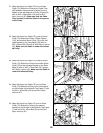
27. Wrap the Dip Cable (74) under a 90mm Pulley
(78). Attach the Pulley and a Cable Trap (68)
between the second set of holes from the top of
the Pulley Plates (63) with an M10 x 50mm Bolt
(100) and an M10 Nylon Locknut (87). Make sure
that the Cable Trap is turned to hold the Cable
in place.
24
25
26
27
Cable Assembly
IMPORTANT: Refer to the CABLE DIAGRAMS
on page 32 for help identifying the cables.
Do not overtighten the bolts and nuts attach-
ing the pulleys; the pulleys must be able to
turn freely.
74
87
141
144
141
61
101
6
78
78
74
137
127
137
87
91
78
87
87
74
78
68
63
100
101
6
91
74
61
74
87
91
23