ENG-11
Before use
Continue
When the speed sensor is not positioned properly in respect to the two *
magnets (in both Steps 2 and 3), move the speed sensor back and forth so
that it is positioned properly. After you move the speed sensor, adjust the
position so that the two magnets face the relevant sensor zone.
After adjustment, tighten the nylon ties firmly to secure the speed sensor.
4.
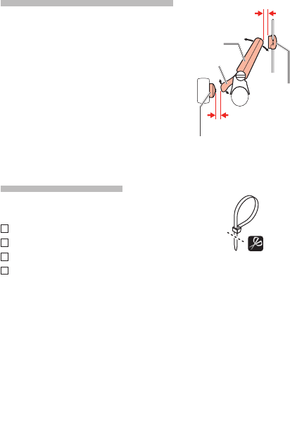
1-3.Adjust the distance to the magnet
Adjust the distance between the wheel
1.
magnet and the SPEED side of the speed
sensor to be about 3 mm. After adjustment,
tighten the set screw on the SPEED side.
Adjust the distance between the cadence
2.
magnet and the CADENCE side of the speed
sensor to be about 3 mm. After adjustment,
tighten the set screw on the CADENCE side.
For steel axle pedals, the cadence magnet can *
be installed onto the end face of the pedal
axle. Make sure to remove the double-sided
tape from the magnet when doing this.
1-4.Securing various parts
Tighten the speed sensor, set screw, and mag-
net firmly, and check for any looseness.
Speed/Cadence sensor nylon ties
Speed and Cadence sensor screws
Wheel magnet screw
Cadence magnet
Wheel
magnet
Cadence magnet
SPEED
CADENCE
About 3 mm
About 3 mm
Cut extra length of the
nylon tie with scissors.


