2100-444-003A
Page 85
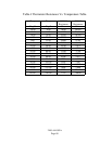
will correspond with the Humidity
according to Table 7.
Discharge Air Sensor #1 or #2 Check Sensor Output Determine the Temperature of the
discharge air. Remove plug in connector
J2 from the TCS22 controller. With a
Digital VOM, check the resistance
between Terminal #4 and Terminal #5
on the low voltage terminal block of the
A/C unit. The resistance will
correspond with the Temperature of the
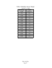
sensor according to Table 6.
Dirty Filter Sensor #1 or #2 Check Output Remove plug in connector J2 from the
TCS22 controller. Observe Filter flag
status of the A/C unit. If the Change
Filter flag is not visible, then there
should be no continuity between
terminals #6 and #7 of the A/C unit low
voltage terminal block. If the Change
Filter flag is visible, then there should be
continuity between terminals #6 and #7
of the A/C unit. voltage terminal block.
Compressor Current Sensor
#1 or #2
Check Sensor Output Remove plug in connectors J1, J2 and J4
from the TCS22 controller. Connect a
jumper wire between R and G of the
A/C unit low voltage terminal block to
operate the blower. Observe the status
of the compressor current sensor LED.
The LED should not be on. Connect a
jumper wire between R and Y of the
A/C unit low voltage terminal block to
operate the compressor. When the
compressor is running, the LED should
flash rapidly (Approx. 4 times per
second). If the Led is flashing slowly
(Approx. 2 times per second), adjust
potentiometer on the sensor until the
LED begins flashing rapidly when
compressor is running.
Blower Airflow Sensor #1 or
#2
Check Sensor Output Remove plug in connectors J1, J2 and J4
from the TCS22 controller. Check
continuity between terminal #8 and #9
of the A/C unit low voltage terminal
block. This should be an Open circuit
with the Blower off. Connect a
j
um
p
er


