


2100-444-003A
Page 84
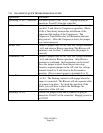
to F on the terminal strip on controller
with the Unit #1 Economizer light ON.
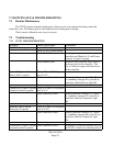
Check operation of the
Economizer
Connect a jumper wire on the A/C unit
low voltage terminal strip from R to G.
Connect another jumper wire on the A/C
unit low voltage terminal strip from E to
F (Never connect power to these
terminals) and check for Economizer
operation.
Modem not responding Check status of lights on
Modem
Reset Modem
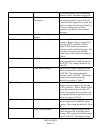
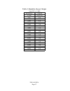
Zone Temperature Sensor Check Sensor output Determine the Temperature of the
structure. Remove plug in connector J1
from the TCS22 controller. With a
Digital VOM, check the resistance
between pins #3 and #6 in the plug. The
resistance will correspond with the
Temperature of the sensor according to
Table 6.
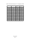
Zone Humidity Sensor Check Sensor Input Check the AC voltage supply to the
Sensor output board, inside the door of
the TCS22. The voltage should be 24
Volts AC
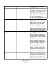
Check Sensor Output Check the DC output voltage from the
sensor output board, inside the door of
the TCS22. The voltage should be
between 1 and 5 Volts DC. The Output
voltage will correspond with the
Humidity according to Table 7.
OutDoor Temperature Sensor Check Sensor Output Determine the Outdoor Temperature.
Remove plug in connector J1 from the
TCS22 controller. With a Digital VOM,
check the resistance between pins #13
and #14 in the plug. The resistance will
correspond with the Temperature of the
sensor according to Table 6.
OutDoor Humidity Sensor Check Sensor Input Check the AC voltage supply to the
Sensor output board, inside the sensor
housing. The voltage should be 24 Volts
AC
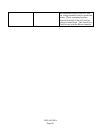
Check Sensor Output Check the DC output voltage from the
sensor output board, inside the sensor
housing. The voltage should be between
1 and 5 Volts DC. The Out
p
ut volta
g
e