2100-444-003A
Page 11
3.0 INSTALLATION
This section discusses mounting and wiring
of the TCS22 into the building. Also included is an
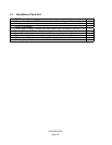
installation checklist to be completed by the
installing contractor. See installation instructions
supplied with the Bard Wall-Mount air
conditioners for information on installing the air
conditioners.
This controller should be installed and
serviced by a qualified service technician only.
3.1 Mounting
TCS22 should be mounted on a flat vertical
surface four (4) to six (6) feet from the floor of the
building. When choosing a suitable location take
into consideration that the electrical connections
can be made from the back or top of the TCS22.
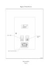
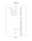
See Figure 3 for rear electrical entrance locations.
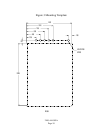
The TCS22 is secured to the wall with
four (4) - 1/4 inch fasteners with flat washers.
Hollow wall anchors or lag bolts are suitable as
dictated by the wall construction. See Figure 3 for
a bolt pattern layout drawing.
3.2 Wiring
Electrical connections can be made from
the back or top of the TCS22. All wiring should
exit the TCS22 in conduit. Use the supplied wire
ties and cable holders to route unit low voltage,
communication, and sensor wiring neatly. Avoid
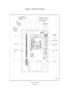
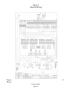
looping excess wire. See Figure 2 for suggested
conduit connections.
Never connect or disconnect wiring from the
controller with power connected to the controller
or to either of the Bard Wall-Mount air-
conditioners.
3.2.1 HIGH VOLTAGE WIRING
IMPORTANT: High voltage wiring must
not be run in the same conduit as low voltage
control or sensor wiring. Failure to comply with
this requirement will result in poor or no remote
communication and/or in inaccurate sensor
reading.
Supply power is 208/240 VAC, 50/60 Hz,
1 Phase at 3 amps minimum circuit ampacity. A 3
amp circuit breaker is supplied as part of the
TCS22. This circuit breaker is for internal circuit
protection only and cannot be used as a disconnect.
Supply wire size should be 18 ga. or larger. Use
Copper Conductors Only. All wiring must comply
with the applicable sections of the National
Electrical Code ( NEC) and any applicable local
codes.
The TCS22 is shipped for 240 VAC
operation . For 208 Volt operation change both
transformer primaries in the TCS22 to the 208 volt
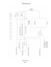
tap. See Wiring Diagram. The acceptable operating
voltage ranges for the 240 and 208 volt taps are:
Tap Range
240 253-216
208 220-187
Connect the high voltage power supply to
Terminal Block TB2. Connect ground wire to the
ground connector provided. TCS22 must be
grounded for proper operation. Failure to ground
the controller may cause erratic controller
operation and inaccurate sensor operation. See
Figure 2 and the wiring diagram.
! WARNING
_________________________________
•HAZARD OF ELECTRIC SHOCK.
•ELECTRIC SHOCK CAN RESULT IN
SERIOUS INJURY OR DEATH.
•DISCONNECT THE REMOTE ELECTRIC
POWER SUPPLIES BEFORE SERVICING.


