


9
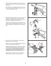
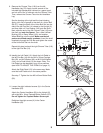
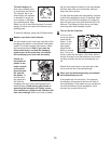
11. Loosen the eight indicated screws (A) in the Center
Handlebar (63).
Attach the Center Handlebar (63) to the Upright (2)
with eight M6 x 16mm Tapered Button Screws (107).
Do not tighten the Tapered Button Screws yet.
Retighten the eight screws (A) in the Center
Handlebar (63).
11
63
2
107
107
A
10
15
14
20
99
12
13
144
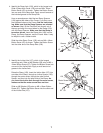
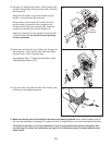
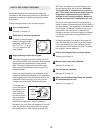
10. Identify the Left Pedal (13). Attach the Left Pedal to
the left Flex Bar (14) with an M10 x 35mm Carriage
Bolt (20), an M10 Washer (99), an M10 Split Washer
(144), and a Pedal Knob (15) as shown. Note: The
Left Pedal can be attached in any of five positions
(see HOW TO ADJUST THE PEDALS on page 11).
Attach the Right Pedal (12) in the same way. Make
sure that both Pedals are in the same position.
See step 7. Tighten the four M8 x 43mm Button Bolts
(50).
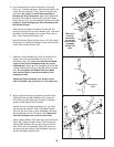
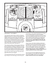
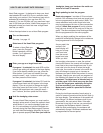
9. Remove the Chrome Tube (118) from the left
Handlebar Leg (79). Apply a small amount of the
i
ncluded high-temperature lubricant to a paper towel,
and rub a thin film of lubricant onto the Chrome Tube.
T
hen, reinsert the Chrome Tube into the Handlebar
Leg.
See the drawing at the right and the inset drawing.
Apply a thin film of grease to the shaft of a Union Bolt
Set (27). Insert the shaft of the Union Bolt Set into the
side of the left Flex Bar (14) closest to the Upright (2),
and then slide a 4.7mm Spacer (143) onto the shaft.
Next, slide the end of the left Chrome Tube (118) onto
the shaft and
onto the Spacer. Then, slide a Wheel
Bushing (28), a Ramp Wheel (119), and another
Wheel Bushing onto the shaft.
Make sure that all
parts are oriented exactly as shown. Insert the shaft
completely through the Flex Bar and tighten the screw
of the Union Bolt Set into the shaft.
Repeat this step to attach the right Chrome Tube (118)
to the right Flex Bar (14).
9
2
L
ubricate
79
2
7
118
143
119
118
27
28
28
27
Grease
Shaft
Screw
14
143
28
28
118
1
19
14
27
14
14