


8
8
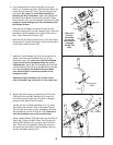
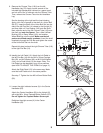
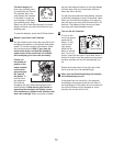
8. Apply a generous amount of grease to the Pivot Axle
(108) and to the two M8.5 W
ashers (53). Insert the
Pivot Axle into the Upright (2) and center it. Reapply
grease to both sides of the Pivot Axle.
Identify the Left and Right Handlebars (9, 10), which
are marked with stickers. Slide a Handlebar Spacer
(25) onto the short tube on each Handlebar
, and slide
the Handlebars onto the Pivot Axle (108).
Make sure
that the Handlebars are on the correct sides.
Place a Wave Washer (150) onto each end of the Pivot
Axle (108). Tighten an M8 x 25mm Patch Screw (22)
with an M8.5 W
asher (53) into each end of the Pivot
Axle. Orient the two Handlebar Caps (23) as shown,
and press the small tabs on the Handlebar Caps into
the two Handlebar Spacers (25).
9
23
22
23
22
53
53
150
150
25
10
2
108
Grease
Grease
25
Tube
Tube
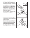
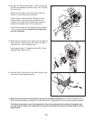
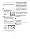
7. Identify the Left Handlebar (9), which is marked with a
sticker. Insert the Left Handlebar into one of the
Handlebar Legs (79);
make sure that the Handlebar
Leg is turned so the hexagonal holes are on the
indicated side. Attach the Left Handlebar with two M8
x 43mm Button Bolts (50) and two M8 Nylon Locknuts
(46). Do not tighten the Button Bolts yet. Make
sure that the Nylon Locknuts are seated in the
hexagonal holes.
Attach the Right Handlebar (not shown) to the
other Handlebar Leg (not shown) in the same way.
7
9
79
Hexagonal
Holes
50
46
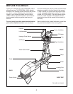
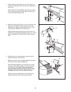
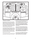
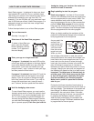
6
6. Have another person hold the Upright (2) near the
Frame (1). Connect the Upper Wire Harness (86) to the
L
ower Wire Harness (87). Next, slide the Upright onto
the Frame.
Be careful to avoid disconnecting or
p
inching the Wire Harnesses.
A
ttach the Upright with
two M8 x 54mm Button Screws (33), two M8 x 38mm
Button Screws (70), and four M8 Split Washers (94).
Be
careful to avoid damaging the Wire Harnesses with
the Button Screws.
Hold the Left and Right Handlebar Covers (26, 29)
around the Upright (2) and the indicated tube. Press the
Handlebar Covers together and connect them with an
M4 x 16mm Round Head Screw (45).
Hold the Left and Right Upright Covers (34, 38) around
the Upright (2). Attach the Upright Covers with two M4 x
14mm Round Head Screws (93).
26
9
3
93
34
38
86
2
Tube
1
87
94
70
33
94
94
94
29
45
Make sure
the wire
harnesses
do not get
pinched and
damaged
during this
step.