


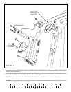
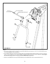
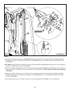
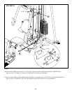
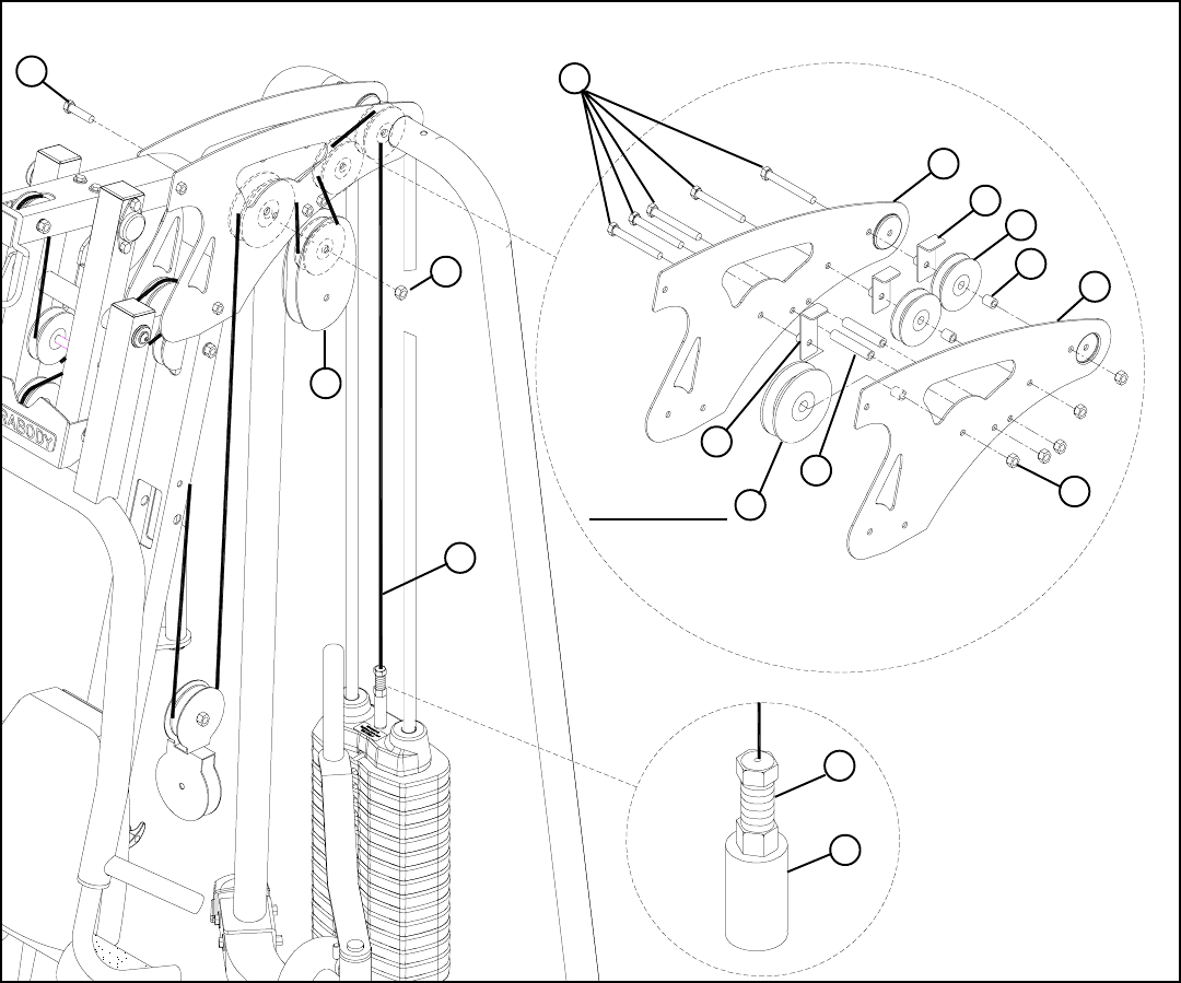
STEP 17:
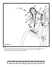
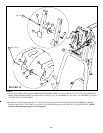
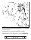
FIGURE 17
18
• Route the LAT CABLE (AM) around one 4-1/2” PULLEY (36) and assemble the PULLEY to the LEFT (D) and RIGHT (E) BOOM
PLATES using one 3/8 X 3-3/4” BOLT (6), one LONG “L” CABLE BRACE (S), one 1” SPACER (24) and one 3/8” LOCK NUT (19).
See FIGURE 17.
• Route the LAT CABLE (AM) around one 3-1/2” PULLEY (35) and assemble two FLOATING PULLEY PLATES (AB) to the 3-1/2” PULLEY
(35) using one 3/8 X 1-3/4” BOLT (11) and one 3/8” LOCK NUT (19). See FIGURE 17. (NOTE: Make sure the cable runs in the grooves
of the pulleys.)
• SECURELY assemble two PLASTIC SLEEVES (34) to the LEFT (D) and RIGHT (E) BOOM PLATES using two 3/8 X 3-3/4” BOLTS (6)
and two 3/8” LOCK NUTS (19) as shown in FIGURE17.
• Route the LAT CABLE (AM) over two 3-1/2” PULLEYS (35) and assemble the PULLEYS to the LEFT (D) and RIGHT (E) BOOM
PLATES using two 3/8 X 3-3/4” BOLTS (6), two SHORT “L” CABLE BRACES (R), two 15/16” SPACERS (24) and two3/8” LOCK
NUTS (19). See FIGURE 17.
• Screw the threaded end of the LAT CABLE (AM) into the end of the HEAD PLATE ASSEMBLY (AF) .See FIGURE 17.
3/8 X 3-3/4” 6
11 3/8 X 1-3/4”
34
36
AM
19
AB
35
R
D
E
24
19
AF
AM
S
4-1/2” PULLEY