


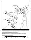
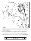
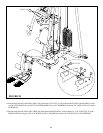
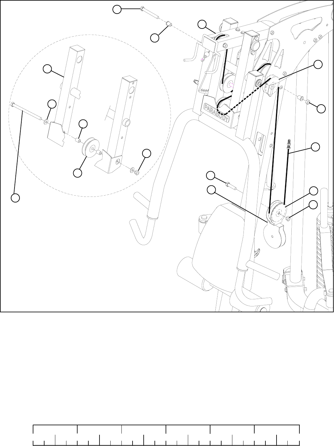
STEP 16:
FIGURE 16
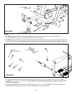
• Route the LAT CABLE (AM) through the PRESS ARM SUPPORT FRAME (X) and assemble one 3-1/2” PULLEY (35) to the FRAME
PRESS ARM SUPPORT FRAME (X) using one 3/8 X 8” BOLT (3), two 3/8” WASHERS (18), two 3/8 X 1-1/4” SPACERS (25) and one
3/8” LOCK NUT (19). See FIGURE 16.
3 3/8 X 8”
X
25
AM
19
18
35
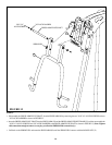
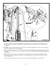
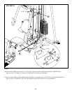
• Route the LAT CABLE (AM) around one 3-1/2” PULLEY (35) and assemble the PULLEY to the DOUBLE FLOATING PULLEY
BRACKET (AA) using one 3/8 X 1-3/4” BOLT (11) and one 3/8” LOCK NUT (19). See FIGURE 16. (NOTE: Make sure the cable
runs in the grooves of the pulleys.)
17
0
1
2
345
6
1/2 1/2 1/2 1/2 1/2 1/2
3/8 X 3-3/4” 6
3/8 X 1-3/4” 11
A
19
35
35
19
AA
26
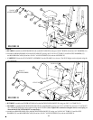
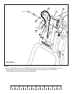
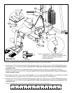
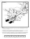
• Route the LAT CABLE (AM) through the FRAME (A) and assemble one 3-1/2” PULLEY (35) to the FRAME (A) using one
3/8 X 3-3/4” BOLT (6), two 3/8 X 1-1/16” FLANGE SPACERS (26) and one 3/8” LOCK NUT (19). See FIGURE 16.