


12
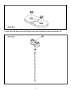
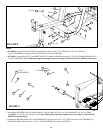
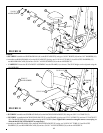
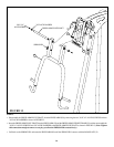
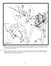
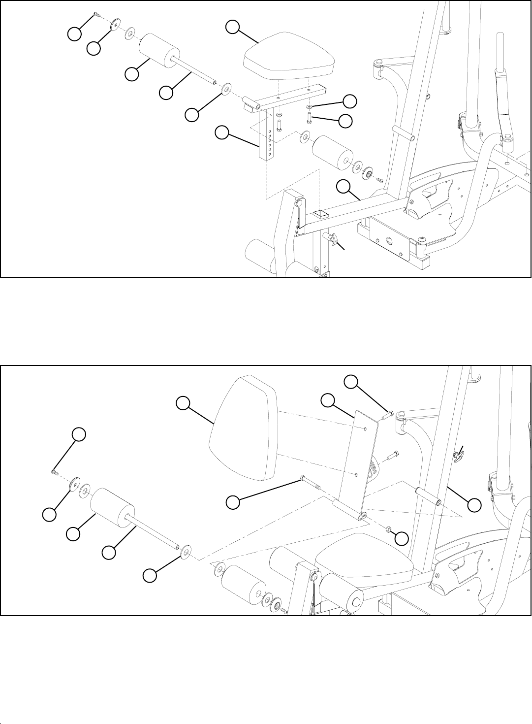
STEP 10:
• SECURELY assemble one SEAT/BACK PAD (AI) to the SEAT ADJUST (J) using two 3/8 X 2” BOLTS (10) and two 3/8” WASHERS (18).
FIGURE 10
J
AI
• CAREFULLY insert the SEAT ADJUST ASSEMBLY into the FRAME (A) as shown. The SEAT height can be adjusted using the
PLUNGER PIN.
AJ
30
18
33
U
PLUNGER
PIN
10 3/8 X 2”
• Assemble two ROLLER PADS (AJ) to the SEAT ADJUST (J) using one 3/4 X 18-1/8” TUBE (U), four PLASTIC WASHERS (33)
two ROLLER PAD CAPS (30) and two 5/16 X 1” ALLEN SCREWS (38) as shown in FIGURE 10.
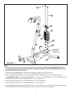
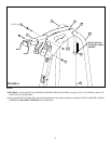
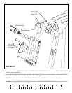
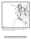
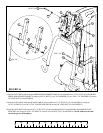
STEP 11:
FIGURE 11
A
• SECURELY assemble one SEAT/BACK PAD (AI) to the BACK INCLINE ADJUST (W) using two 3/8 X 1-1/4” BOLTS (12).
• SECURELY assemble the BACK INCLINE ADJUST (W) to the FRAME (A) using one 1/2 X 5-3/4” BOLT (1) and one 1/2” LOCK NUT
(20). The BACK PAD angle can be adjusted using the PLUNGER. (Note: Tighten this connection enough to remove excess play yet
allow the BACK INCLINE ADJUST to rotate freely.)
• Assemble two ROLLER PADS (AJ) to the BACK INCLINE ADJUST (W) using one 3/4 X 20-3/8” TUBE (V), four PLASTIC
WASHERS (33) two ROLLER PAD CAPS (30) and two 5/16 X 1” ALLEN SCREWS (38) as shown in FIGURE 11.
PLUNGER
PIN
3/8 X 1-1/4” 12
1/2 X 5-3/4” 1
AJ
30
AI
W
33
V
A
20
38
5/16 X 1”
ALLEN SCREW
38
5/16 X 1”
ALLEN SCREW