


13
0
1
2
345
6
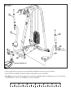
1/2 1/2 1/2 1/2 1/2 1/2
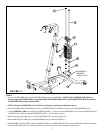
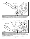
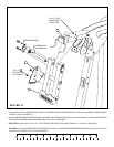
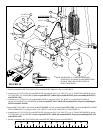
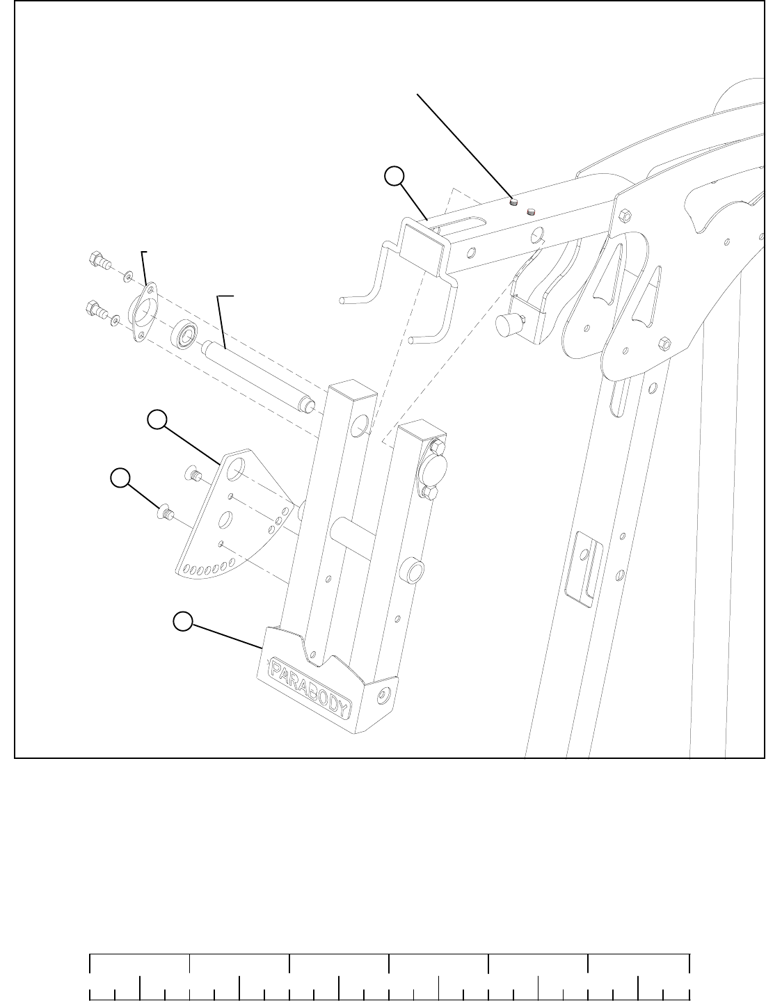
STEP 12:
• SECURELY tighten the two 5/16 X 1/4” SET SCREWS (PRE-INSTALLED)on the FRAME (A) as shown in FIGURE 12.
• Insert the PRESS ARM SUPPORT PIVOT thru the PRESS ARM SUPPORT FRAME (X) and the FRAME (A). Assemble the BEARING
BLOCKS to the PRESS ARM SUPPORT FRAME (X) as shown in FIGURE 12.
3/8 X 1” 16
FLAT HEAD
ALLEN BOLT
PRESS ARM
SUPPORT PIVOT
A
Y
• Disassemble one of the BEARING BLOCKS from the PRESS ARM SUPPORT FRAME (X) and remove the PRESS ARM SUPPORT
PIVOT as shown in FIGURE 12.
FIGURE 12
5/16 X 1/4” SET
SCREW (PRE-
INSTALLED)
X
BEARING BLOCK
• SECURELY assemble the PRESS ARM ADJUSTMENT PLATE (Y) to the PRESS ARM SUPPORT FRAME (X) using two 3/8 X 1” FLAT
HEAD ALLEN BOLTS (16) as shown in FIGURE 12.