16
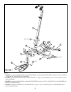
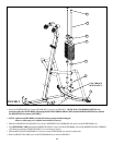
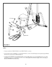
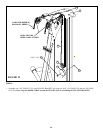
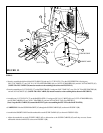
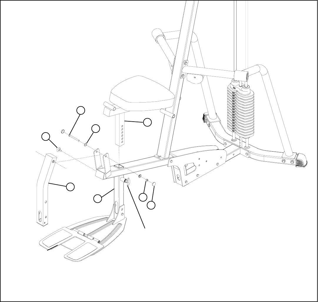
• Securely assemble the 3 PRONG KNOB (43) to the FRONT BASE (1) as shown.
• Insert the SEAT ADJUST ASSEMBLY (7) into the FRONT BASE (1) as shown. The SEAT height can be adjusted using the SPRING
PIN and can be secured with the 3 PRONG KNOB (43).
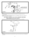
FIGURE 8
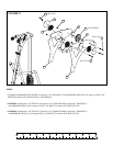
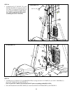
STEP 8:
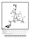
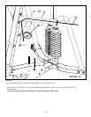
• Assemble the LEG PEDESTAL (8) to the FRONT BASE (1) using two RH CAPS (47), one 1/2 X 104mm BOLT (58), two 1/2” RH
WASHERS (46), and one 1/2” LOW HEIGHT LOCK NUT (62). (Note: Tighten this connection enough to remove excess play yet
allow the LEG PEDESTAL to rotate freely.)
1/2 X 104mm
47
62
1
8
58
46
3
43
SPRING PIN


