15
STEP 6:
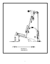
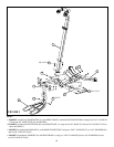
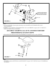
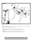
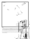
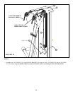
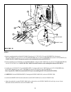
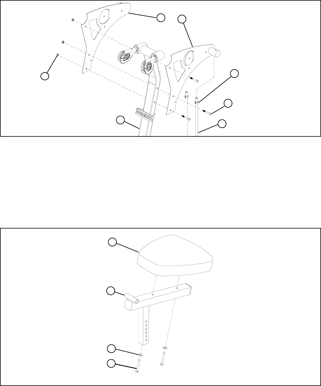
• Swing the GUIDE RODS (18) into the guide rod bushings in each of the RIGHT and LEFT BOOM PLATES (14 & 15)
as shown in FIGURE 6.
• LOOSELY assemble the RIGHT and LEFT BOOM PLATES (14 & 15) to the UPRIGHT (2) using three 3/8 X 3-3/4” BOLTS (57)
and three 3/8” LOCK NUTS (63). See FIGURE 6.
STEP 7:
3/8 X 3-3/4”
2
63
18
14
FIGURE 7
7
16
FIGURE 6
3/8 X 3”
64
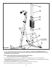
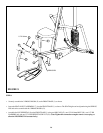
• Slide the SHAFT COLLARS (36) to the top of the GUIDE RODS (18) and tighten set screws as shown in FIGURE 6.
36
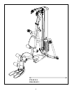
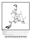
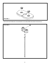
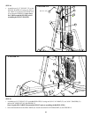
• SECURELY assemble one SEAT PAD (16) to the SEAT ADJUST (7) using two 3/8 X 3” BOLTS (67) and two 3/8” WASHERS (64).
See FIGURE 7.
57
15
67
SECURELY TIGHTEN ALL NUTS AND BOLTS BEFORE
PROCEEDDING TO NEXT STEPS
TIGHTEN AFTER FRAME
NUTS AND BOLTS HAVE
BEEN SECURELY TIGHTEN


