


8
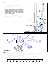
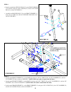
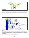
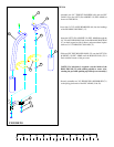
FIGURE 8
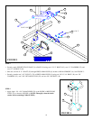
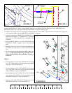
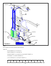
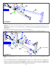
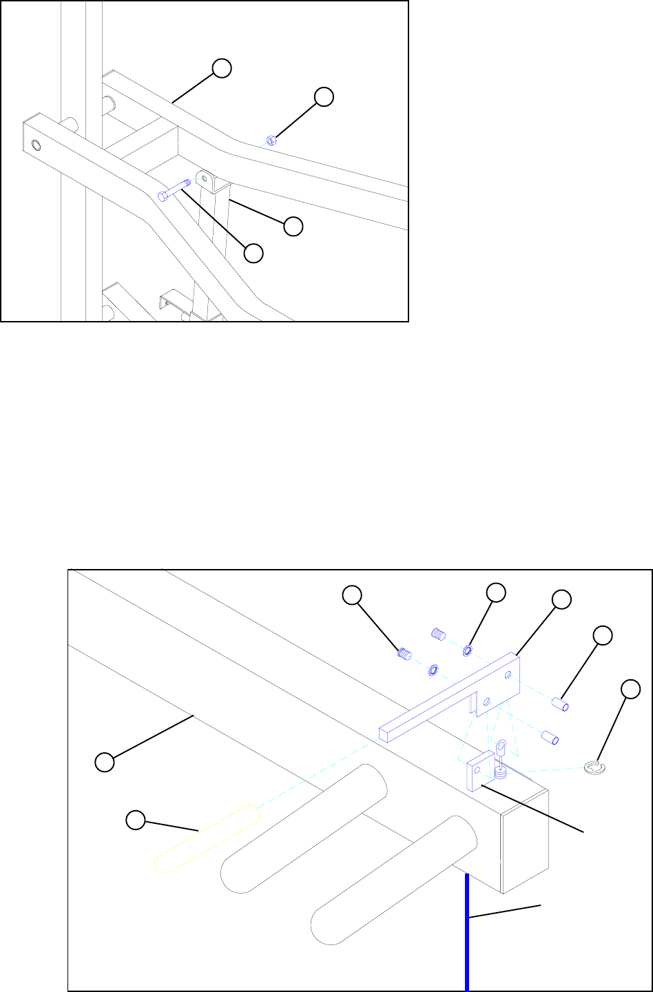
FIGURE 7
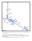
• Attach ADJUSTMENT SLIDE (6) to PRESS ARM
(8) using one 1/2 X 3-1/2" BOLT (43), and 1/2" LOW
HEIGHT LOCKNUT (50). (NOTE: Securely
tighten, then back nut off 1/4 turn to allow the
PRESS ARM (8) to rotate freely.)
STEP 7
STEP 8
• Insert the PUSH/PULL CABLE through the bottom of the PRESS ARM (8) up to the CONTROL LEVER (59) and hold in place
with one E-RING (62) as shown in FIGURE 8.
• Securely assemble the PUSH/PULL CABLE to the CONTROL LEVER (59) using one 3/8 IN. JOINT CONNECTOR CAP (61),
one #8 INT. TOOTH LOCK WASHER (63), and one 8-32 X 3/16 IN. SCREW (60) as shown in FIGURE 8.
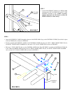
• Slide one 4” VINYL SLEEVE (64) over the CONTROL LEVER (59). Then SECURELY assemble the CONTROL LEVER (59)
to the TAB on the PRESS ARM (8) using one 3/8” JOINT CONNECTOR CAP (61), one #8 INT. TOOTH LOCK WASHER
(63), and one 8-32 X 3/16 IN. SCREW (60) as shown in FIGURE 8.
50
8
43 1/2 X 3-1/2”
6
64
TAB
8
60
61
PUSH/PULL
CABLE
63
59
62
1/2” LOW
HEIGHT