


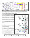
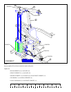
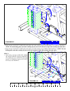
FIGURE 22
15
52
10
18
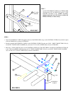
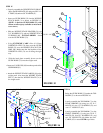
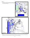
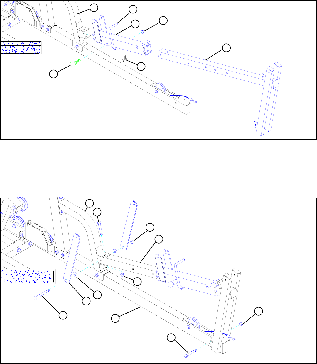
FIGURE 21
16
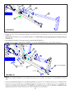
STEP 21
• Slide the WOLFF SLEEVE (2) over the BENCH FRAME (15). (NOTE: Make sure the spring pin barrel is facing as shown in
FIGURE 21.)
• Slide the BENCH FRAME (15) between the angles on the FRAME SUPPORT (1).
• Securely assemb1e one 3/8” SPRING PIN ASSEMBLY (71) and one THUMBSCREW (95) to the WOLFF SLEEVE (2).
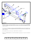
STEP 22
• Attach two 2 X 16-1/2” PLATES (18) to the BENCH FRAME (15) using one 1/2 X 3-1/2” BOLT (43), two 1/2” WASHERS (52),
and one 1/2” LOCKNUT (49). Make sure 1/2” WASHER (52) is on inside of plate as shown on FIGURE 22. (NOTE: Securely
tighten, then back nut off 1/4 turn to allow the 2 X 16-1/2” PLATES (18) to rotate freely.)
• Securely fasten BENCH FRAME (15) to the BASE (10) using one 1/2 X 3” BOLT (42) and one 1/2” LOW HEIGHT LOCKNUT
(50).
• Slide the 1/2” DIA U-PIN (55) through the bushing in the WOLFF SLEEVE (2) then force 1/2” PAL NUT (54) over end of 1/2” DIA
U-PIN (55).
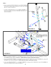
15
2
71
1
54
55
50
1/2 X 3” 42
1/2” LOW HEIGHT
50
43 1/2 X 3-1/2”
42 1/2 X 3”
1
49
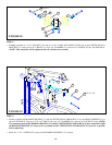
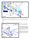
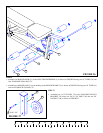
• Securely attach BENCH FRAME (15) to the FRAME SUPPORT (1) using one 1/2” X 3” BOLT (42) and one 1/2” LOCKNUT (49).
95