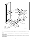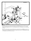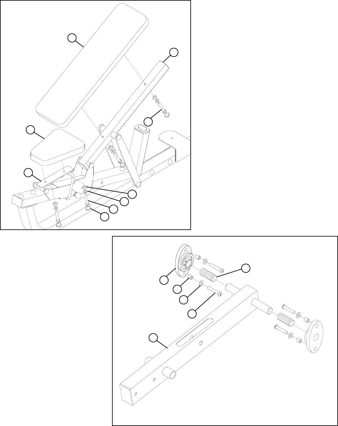
STEP 7:
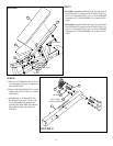
FIGURE 7
9
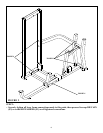
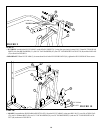
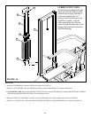
STEP 8:
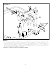
FIGURE 8
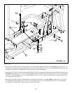
• SECURELY assemble the BACK PAD (16) to the BACK
PAD SUPPORT (7) using two BLACK RH CAPS (52),
two 3/8 X 73mm BOLTS (41), two 3/8” SAE WASHERS
(50) and two 3/8” RH WASHERS (51) as shown in FIG-
URE 7.
50
35 3/8 X 32mm
41 3/8 X 73mm
51
7
16
17
52
BLACK
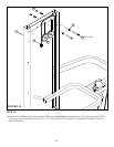
• SECURELY assemble theSEAT PAD (17) to the SEAT
PAD SUPPORT (3) using two BLACK RH CAPS (52),
two 3/8 X 32mm BOLTS (35), two 3/8” SAE WASHERS
(50) and two 3/8” RH WASHERS (51) as shown in FIG-
URE 7.
3/8 X 76mm 46
BUTTON HEAD
5
29
18
• Slide two ACCORIDIAN SLEEVES (29)
over the shafts of the PIVOT ARM (5) as
shown in FIGURE 8.
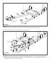
• Slide two PILLOW BLOCKS (18) over the
shafts of the PIVOT ARM (5) as shown
in FIGURE 8.
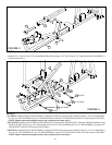
• Assemble four 3/8 X 76mm BUTTON
HEAD BOLTS (46), four 3/8” BLACK
FLAT WASHERS (48) and four PIL-
LOW BLOCK SPACERS (30) to the the
PILLOW BLOCKS (18)
as shown in
FIGURE 8.
BLACK 48
30
3


