


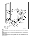
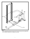
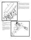
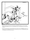
STEP 5:
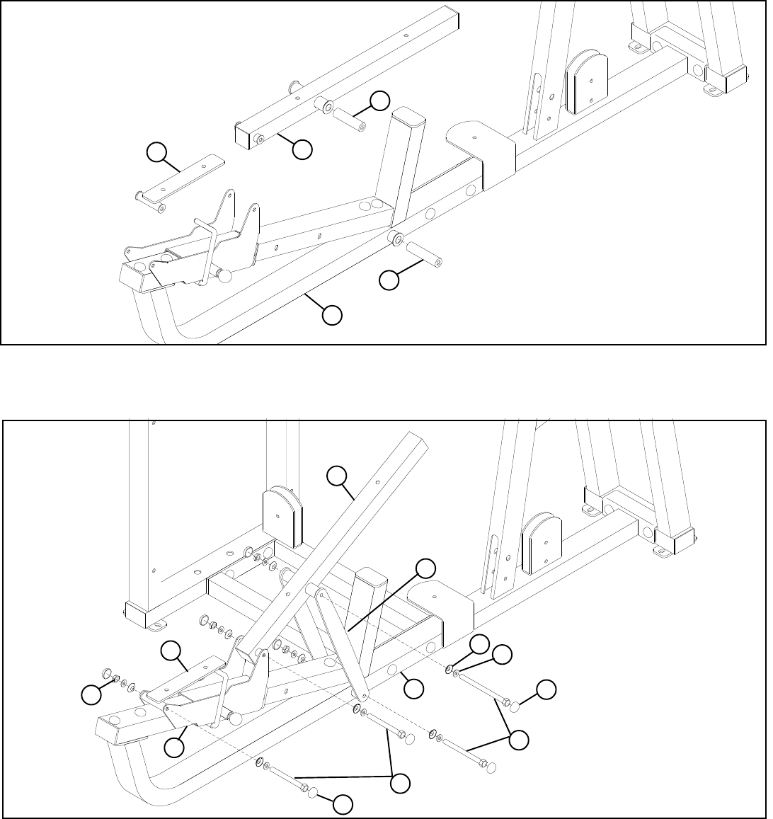
FIGURE 5
8
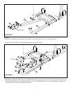
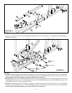
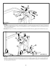
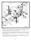
STEP 6:
FIGURE 6
• Insert one 5-1/2” PIVOT SHAFT (27) into the PRESS FRAME (8) and one 5-1/2” PIVOT SHAFT (27) into the BACK PAD SUPPORT (7)
as shown in FIGURE 5.
7
27
8
27
3
• SECURELY assemble two MULTI PRESS ADJUST PLATES (11) to the BACK PAD SUPPORT (7) and to the PRESS FRAME (8) using
four BLACK RH CAPS (52), two 3/8 X 164mm BOLTS (44), four 3/8” SAE WASHERS (50), four 3/8” RH WASHERS (51) and two 3/8”
LOW HEIGHT LOCK NUTS (49) as shown in FIGURE 6.
• SECURELY assemble the SEAT PAD SUPPORT (3) to the SEAT ADJUST (6) using two BLACK RH CAPS (52), one 3/8 X 106mm BOLT
(43), two 3/8” SAE WASHERS (50), two 3/8” RH WASHERS (51) and one 3/8” LOW HEIGHT LOCK NUT (49) as shown in FIGURE 6.
(NOTE: Tighten connections enough to remove slop, yet allow part to rotate freely.)
43 3/8 X 106mm
44 3/8 X 164mm
11
49
51
50
8
7
3
52 BLACK
52 BLACK
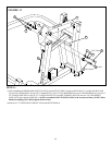
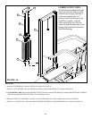
• SECURELY assemble the BACK PAD SUPPORT (7) to the SEAT ADJUST (6) using two BLACK RH CAPS (52), one 3/8 X 106mm BOLT
(43), two 3/8” SAE WASHERS (50), two 3/8” RH WASHERS (51) and one 3/8” LOW HEIGHT LOCK NUT (49) as shown in FIGURE 6.
(NOTE: Tighten connections enough to remove slop, yet allow part to rotate freely.)
6