


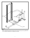
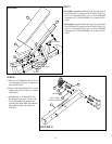
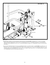
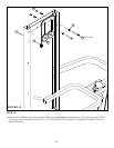
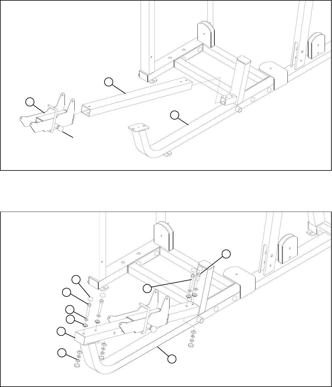
STEP 3:
FIGURE 3
7
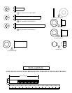
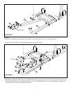
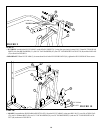
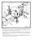
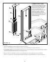
STEP 4:
FIGURE 4
• Pull back on the SPRING PIN and slide the SEAT ADJUST (6) over the SLIDE TUBE (12) as shown in FIGURE 3.
• SECURELY assemble the SLIDE TUBE (12) to the PRESS FRAME (8) using seven RH CAPS (53), two 3/8 X 67mm BOLTS (39), one
3/8 X 61mm BOLT (38), one 3/8 X 25mm BOLT (34), seven 3/8” SAE WASHERS (50), seven 3/8” RH WASHERS (51) and three 3/8”
LOW HEIGHT LOCK NUTS (49) as shown in FIGURE 4.
6
8
12
SPRING PIN
• Assemble the SLIDE TUBE (12) to the PRESS FRAME (8) as shown in FIGURE 3.
12
51
50
8
49
34 3/8 X 25mm
3/8 X 67mm 39
3/8 X 61mm 38
53