


31
Section 5: Maintenance & Lubrication
12/15/15
SBD3596 & SBD35108 Snow Blowers 370-347M
Table of Contents
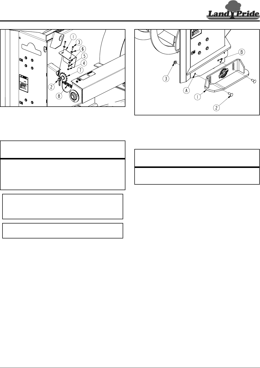
Roller Chain Replacement
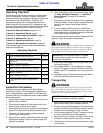
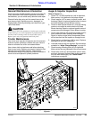
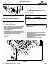
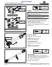
Figure 5-5
Drive Chain
Refer to Figure 5-5:
1. Remove cap screws (#3) and idler guard (#1). Keep
guard and guard hardware for reattachment.
2. Loosen cap screw (#2) and pull up on take-up
sprocket (#7). Remove drive chain (#8).
3. Inspect drive chain for wear or have your nearest
Land Pride service center inspect the drive chain.
4. A worn drive chain will accelerate sprocket wear.
Replace worn drive chain when needed.
5. Install existing or new drive chain as needed. Pull up
on take-up sprocket (#7) and place top chain strand
of drive chain (#8) beneath the take-up sprocket.
6. Push down on take-up sprocket (#7) until vertical
movement in the middle of the bottom chain strand
has 3/8" to 1/2" slack.
7. Hold sprocket in this position and tighten 5/8"-11 cap
screw (#2) to the correct torque.
8. Replace idler guard (#1) with existing 5/16"-18 GR5
bolts (#3), 4 flat washers (#6), spring lock
washers (#5), and hex nuts (#4) as shown.
Tighten hex nuts to the correct torque.
35722
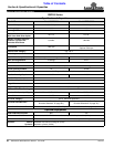
Drive Chain Part Number
Item Part No. Part Description
SBD3596
8 809-238C #60 RC x 118 PITCHES WITH CONNECTOR
SBD35108
8 809-237C #80 RC x 102 PITCHES WITH CONNECTOR
IMPORTANT: Do not over-tension drive chain. A
tight drive chain will overload drive shaft, auger shaft
and bearings. Damage to components due to an
over-tensioned drive chain will void its warranty.
IMPORTANT: Make sure roller chain (#8) is beneath
take-up sprocket (#7) and not above.
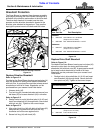
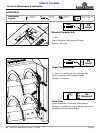
Outer Skid Shoe Replacement (Left-hand shown)
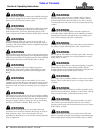
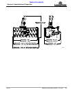
Figure 5-6
Outer Skid Shoes (Optional)
Refer to Figure 5-6:
Inspect outer skid shoes for wear and replace as needed.
1. Place support blocks under Snow Blower grader
blade to hold unit off the ground high enough to
remove skid shoes (#1).
2. Lower Snow Blower onto the support blocks, place
gear selector in park or in neutral with park brake set,
shut engine off, remove switch key, and wait for PTO
to stop running before dismounting tractor.
3. Remove carriage bolts (#2) and left-hand skid
shoe (#1). Save hardware for reattachment of new
skid shoe. Discard old skid shoe.
4. Attach leading end of left-hand skid shoe (#1) to front
hole “A” with 1/2"-13 x 1 1/4" GR5 carriage bolt (#2)
and hex flange lock nut (#3).
5. Attach trailing end of skid shoe (#1) to hole “B” with
1/2"-13 x 1 1/4" GR5 carriage bolt (#2) and hex flange
lock nut (#3).
6. Tighten lock nuts (#3) to the correct torque.
7. Repeat steps 3 to 6 above to attach right-hand skid
shoe.
8. See “Outer Skid Shoe (Optional)” on page 22 for
detailed adjustment instructions.
35716
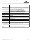
Outer Skid Shoe Part Numbers
Item Part No. Part Description
1 370-436 OUTER RIGHT-HAND SKID SHOE
1 370-437 OUTER LEFT-HAND SKID SHOE (Shown)