


11
Section 1: Assembly & Set-up
12/15/15
SBD3596 & SBD35108 Snow Blowers 370-347M
Table of Contents
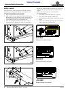
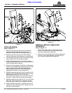
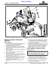
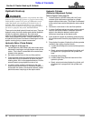
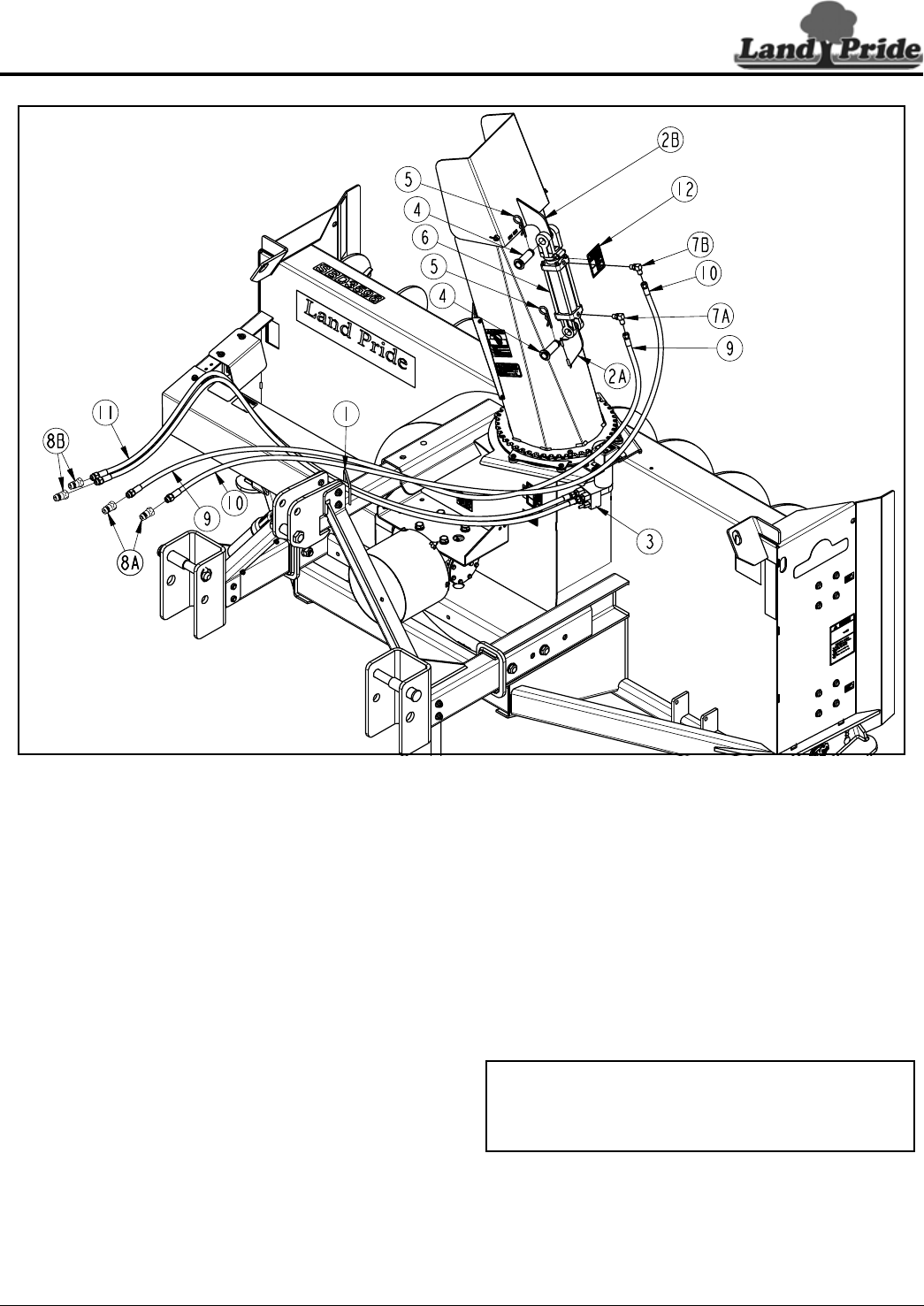
Deflector, Hydraulic Adjustment
(Optional)
Refer to Figure 1-4:
1. Screw quick disconnect couplings (#8A) to hydraulic
hoses (#9 & #10) until tight (quick disconnect
couplings are furnished by customer).
2. Attach 9/16" MORB end with nut of orifice elbows
(#7A & #7B) to ports in hydraulic cylinder (#6). Do not
tighten at this time.
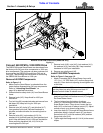
3. Attach the shorter hydraulic hose (#9) to orifice elbow
(#7A) and tighten.
4. Attach the longer hydraulic hose (#10) to orifice
elbow (#7B) and tighten.
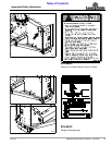
5. Attach base end of hydraulic cylinder (#6) to lower
chute lug (#2A) with 1" x 2 3/4" clevis pin (#4). Secure
clevis pin with hairpin cotter (#5).
6. Attach rod end of hydraulic cylinder (#6) to deflector
lug (#2B) with 1" x 2 3/4" clevis pin (#4). Secure
clevis pin with hairpin cotter (#5).
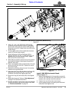
7. Route hydraulic hoses (#9 & #10) through hose
loop (#1).
8. Orient orifice elbows (#7A & #7B) as shown in Figure
1-4 and tighten to ports in hydraulic cylinder (#6).
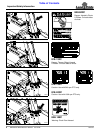
9. Coil Hydraulic hoses (#9 & #10) around Snow Blower
mainframe for safe keeping.
10. Attach High Pressure Fluid Decal 848-747C (#12) on
the back side of the discharge chute and just right of
hydraulic cylinder (#6) as shown. See “Safety
Labels” on page 4 for installation instructions.
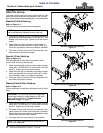
Chute Rotation, Hydraulic Motor
Refer to Figure 1-4:
1. Screw quick disconnect couplings (#8B) to opposite
end of hydraulic hoses (#11) until tight (quick
disconnect couplings are furnished by customer).
2. Route hydraulic hoses (#11) through hose loop (#1).
3. Coil hydraulic hoses (#11) around Snow Blower
mainframe for safe keeping.
IMPORTANT: Adjustment screws on hydraulic
motor (#3) are preset at the factory. Do not change
factory settings. Changing factory settings can
cause structural damage to the Snow Blower.
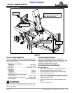
Deflector Adjustment, Hydraulic Option
Figure 1-4
35714