


Cybex 445T Treadmill Owner’s Manual
#2
#4
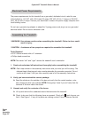
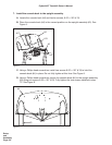
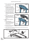
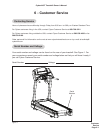
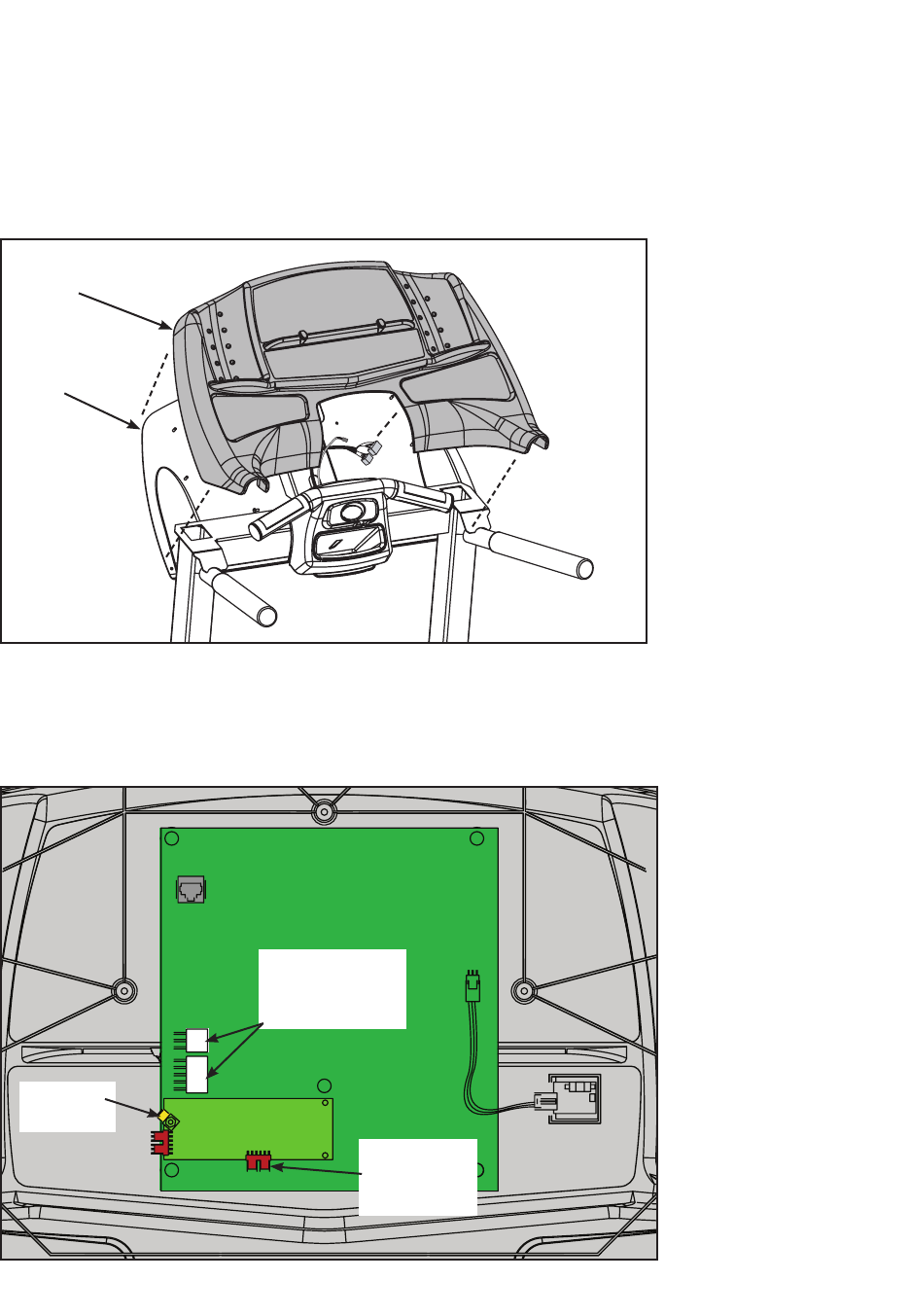
Figure 8
Display
Cable
(2 Connectors)
Contact
Heart Rate
Cable
Ground
Wire
Setup
and
Assembly
Page 5-7
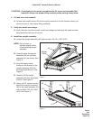
NOTE: If installing the A/V option, refer to the 445T A/V bracket installation instructions
(supplied with the A/V bracket).
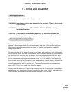
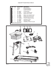
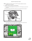
8. Install the console assembly to the console back.
A. Locate the console assembly (#2), two screws, 8-32 x .38” (#13) and nine screws 8-16
x .50” (#14).
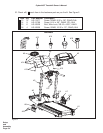
B. Place the console assembly (#2) in position on the console back (#4). See Figure 7.
C. Connect these cables into the display board: the display cable (2 connectors), the
contact heart rate cable and the ground wire. See Figure 8.
Figure 7